|
|
|
Who's Online
There currently are 5987 guests online. |
|
Categories
|
|
Information
|
|
Featured Product
|
|
|
 |
|
|
There are currently no product reviews.
 ;
complete part-lists and pcb layout, schematic diagram is good enlargable,
;
Excellent, fast delivery, excellent product. Good luck!
;
This manual is for the usa model only. But it is clear
, accurate and comprehensive, including board layouts and schematics.
I found it extremely useful for my mitsubishi dp-86da, but the same diagram would also work for the realistic lab5000 and hi fi 80. Thanks.
;
Great to have extra resources for Service Manuals, Now days you can really not trouble shoot efficiently without one , Wayne at IRIONS TV & ELECTRONICS REPAIR Clearwater , Fl. 33755 727-446-7955
 ;
For five bucks you can barely buy a hamburger. Or for the same five bucks you can buy a service manual. Much more useful. (and better for your health, depending on where you buy your hamburgers).
Yes, there are free manual sites out there, but if they don't have what you want, you have to pay.
And five bucks isn't much. Not for full specs, schematics and adjustment and parts replacement procedures.
My only criticism is that grayscale illustrations aren't well rendered, but I've seen worse.
Schematics and text are clear.
I'll be happy to purchase from here again.
Mike
[email protected]
Safety Check after Servicing
Examine the area surrounding the repaired location for damage or deterioration. Observe that screws, parts and wires have been returned to original positions, Afterwards, perform the following tests and confirm the specified values in order to verify compliance with safety standards. 1. Insulation resistance test Confirm the specified insulation resistance or greater between power cord plug prongs and externally exposed parts of the set (RF terminals, antenna terminals, video and audio input and output terminals, microphone jacks, earphone jacks, etc.). See table 1 below. 2. Dielectric strength test Confirm specified dielectric strength or greater between power cord plug prongs and exposed accessible parts of the set (RF terminals, antenna terminals, video and audio input and output terminals, microphone jacks, earphone jacks, etc.). See table 1 below. 3. Clearance distance When replacing primary circuit components, confirm specified clearance distance (d), (d�) between soldered terminals, and between terminals and surrounding metallic parts. See table 1 below. Chassis Fig. 8 4. Leakage current test Confirm specified or lower leakage current between earth ground/power cord plug prongs and externally exposed accessible parts (RF terminals, antenna terminals, video and audio input and output terminals, microphone jacks, earphone jacks, etc.). Measuring Method : (Power ON) Insert load Z between earth ground/power cord plug prongs and externally exposed accessible parts. Use an AC voltmeter to measure across both terminals of load Z. See figure 9 and following table 2.
d
d'
Power cord, primary wire
a
b
Externally exposed accessible part
Z V
c
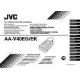
Fig. 9 5. Grounding (Class 1 model only) Confirm specified or lower grounding impedance between earth pin in AC inlet and externally exposed accessible parts (Video in, Video out, Audio in, Audio out or Fixing screw etc.). Measuring Method: Connect milli ohm meter between earth pin in AC inlet and exposed accessible parts. See figure 10 and grounding specifications.
AC inlet
Exposed accessible part
Grounding Specifications Region Grounding Impedance (Z) Z � 0.1 ohm Z � 0.5 ohm USA & Canada Europe & Australia
Earth pin Milli ohm meter
Fig. 10
AC Line Voltage 100 V 100 to 240 V 110 to 130 V 110 to 130 V 200 to 240 V
Region Japan USA & Canada Europe & Australia
Insulation Resistance (R) R � 1 M�/500 V DC 1 M� � R � 12 M�/500 V DC R � 10 M�/500 V DC
Dielectric Strength AC 1 kV 1 minute AC 1.5 kV 1 miute AC 1 kV 1 minute AC 3 kV 1 minute (Class 2) AC 1.5 kV 1 minute (Class 1)
Clearance Distance (d), (d') d, d' � 3 mm d, d' � 4 mm d, d' � 3.2 mm d � 4 mm d' � 8 mm (Power cord) d' � 6 mm (Primary wire)
Table 1 Specifications for each region
AC Line Voltage 100 V 110 to 130 V 110 to 130 V 220 to 240 V
Region Japan USA & Canada
0.15 µF
Load Z
Leakage Current (i) i � 1 mA rms i � 0.5 mA rms
1.5 k�
a, b, c Exposed accessible parts Exposed accessible parts Antenna earth terminals Other terminals
1 k�
Europe & Australia
2 k�
50 k�
i i i i
� 0.7 mA peak � 2 mA dc � 0.7 mA peak �
2 mA dc
Table 2 Leakage current specifications for each region Note: These tables are unofficial and for reference only. Be sure to confirm the precise values for your particular country and locality.
2
S40888-01
|
|
|
> |
|