|
|
|
Who's Online
There currently are 6043 guests online. |
|
Categories
|
|
Information
|
|
Featured Product
|
|
|
 |
|
|
There are currently no product reviews.
 ;
Excellent transaction - clean document received - Thanks a lot
;
Manual is in German but complete. I needed this one to fix a long lasting problem with the internal PSU of the camera. Most of the capacitors begin to leak after a few years wich results in the inability to power on the camera. When you try to turn it on the power led flickers and the unit directly turns off. Thanks to this manual I was able to locate all bad cap's and to dis- and reassemble the camera without any problems.
 ;
We received the manual in a timely manner and it was exactly what we were expecting.
;
Excellant, finally this is want I need and searching for The service manual is fantastic and thank you to owner-manuals.com and its service. Price is reasonable. It's a bit slow on my end in downloading but manage to receive the whole manual without a break. once again, thanks.
;
Very good scanning quality. All schematics are very legible. Worth every cent !
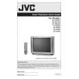
AV-20D304
2.2 DISASSEMBLY PROCEDURE 2.2.1 REMOVING THE REAR COVER (1) Unplug the power plug. (2) As shown in the Fig.1, remove the 9 screws [A]. (3) As shown in Fig.1, remove the 4 screws [B]. (4) Then remove the REAR COVER toward you. 2.2.4 CHECKING THE PW BOARD � Remove the REAR COVER. (1) Pull out the MAIN CHASSIS (refer to REMOVING THE MAIN PWB). (2) Erect the MAIN CHASSIS vertically so that you can easily check the backside of the PW Board. CAUTION: � When erecting the chassis, be careful so that there will be no contacting with other PW Board. � Before turning on power, make sure that the wire connector is properly connected. � When conducting a check with power supplied, be sure to confirm that the CRT EARTH WIRE (BRAIDED ASS�Y) is onnected to the CRT SOCKET PW board. 2.2.3 REMOVING THE SPEAKER � Remove the REAR COVER. (1) As shown in Fig.1, remove the 4 screws [D], then remove the speaker. (2) Follow the same steps when remove the other hand speaker. NOTE: When removing the 4 screws [D] of the speaker, remove the lower side screw first, and then remove the upper one. 2.2.5 WIRE CLAMPING AND CABLE TYING (1) Be sure to clamp the wire. (2) Never remove the cable tie used for tying the wires together. Should it be inadvertently removed, be sure to tie the wires with a new cable tie.
2.2.2 REMOVING THE MAIN PWB � Remove the REAR COVER. (1) Raise the backside of the MAIN PWB, and remove the PWB STOPPER [C] from the cabinet. (2) Withdraw the MAIN PWB backward. (If necessary, remove the wire clamp, connectors etc.)
(No.52103)1-5
|
|
|
> |
|