|
|
|
Who's Online
There currently are 5885 guests online. |
|
Categories
|
|
Information
|
|
Featured Product
|
|
|
 |
|
|
There are currently no product reviews.
 ;
Easy to order the manual. Good quality and fast delivery.
;
The Service Manual for Sansui AU-9500 was very helpfull, in complete and in good printable condition.
Thanks.
;
Dear Sir,
Document is original service document of sharp. I had a problem with the door contacts. Fuses where blown. With the manual in a few minuts is was clear what the problem was.
Manual was of great help.
With kind regards,
Martie Verhoeven
The Netherlands.
 ;
The scan is clear and well readable with very few weaker spots, usually on black background with white letters, but with enough zoom those spots can be read.
Printout is clear, the manual is complete and has all pages scanned.
I would give 5 stars, except that it is not in color, and the schematic and PCB pages are scanned on multiple pages. The document is locked (except printing) so the pages can not be extracted to compose them together for printing on the large plotter
It is worth the price tag.
;
let's say first that i do not need to have a credit for my opinion, i am a retired sparkie and i voluteerd to fix an electronic device for a local "Youthgroup",as no diagram was present i checked the "net" and gambled on this site and paying some fee via PayPall, i was gladly surprised that the manual arrived as was stated, GOOD SHOW, and best wishes, John
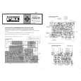
AV-20N4
STATIC CONVERGENCE ADJUSTMENT
1. Input a cross-hatch signal.
2. Using 4-pole convergence magnets, overlap the red and blue lines in the center of the screen (Fig. 1) to turn them to magenta (red/blue).
(FRONT VIEW)
3. Using 6-pole convergence magnets, overlap the magenta (red/ blue) and green lines in the center of the screen to turn them to white.
4. Repeat 2 and 3 above, and make best convergence.
Fig. 1
DYNAMIC CONVERGENCE ADJUSTMENT
1. Move the deflection yoke up and down and overlap the lines in the center. (Fig. 2)
(FRONT VIEW) RED GREEN BLUE
BLUE
RED GREEN BLUE
2. Move the deflection yoke left to right and overlap the lines in the periphery. (Fig. 3)
GREEN RED
3. Repeat 1 and 2 above, and make best convergence.
BLUE GREEN RED
Fig. 2
q After adjustment, fix the wedge at the original position. Fasten the retainer screw of the deflection yoke. Fix the PC magnets with glue.
(FRONT VIEW) GREEN RED BLUE GREEN BLUE RED RED GREEN BLUE
BLUE GREEN RED
Fig. 3
No. 56028
25
|
|
|
> |
|