|
|
|
Who's Online
There currently are 5974 guests online. |
|
Categories
|
|
Information
|
|
Featured Product
|
|
|
 |
|
|
There are currently no product reviews.
 ;
This manual was exactly what i needed and could not find elsewhere. Price is not too high. Great !
;
ecelent I was reciver the service manual soon I fell so happy very complete 100% positive all by this store tanks atte Luis salazar
 ;
A great copy of the manual, and the only one I could find anywhere on the net! The circuit diagrams are easily readable, all component values marked and easy to see. A highly appreciated download!
;
Great Manual. This manual is available no where else. It was exactly what I was looking for.
;
The TEAC A-1500's Service Manual was instrumental in reviving this classic reel-to-reel. Not only does it have the schematics, exploded parts diagram and parts list, it also provided mechanical adjustment information that approximate factory default settings.
AV-20N8
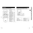
REPLACEMENT OF CHIP COMPONENT
s CAUTIONS
1. 2. 3. 4. Avoid heating for more than 3 seconds. Do not rub the electrodes and the resist parts of the pattern. When removing a chip part, melt the solder adequately. Do not reuse a chip part after removing it.
s SOLDERING IRON
1. Use a high insulation soldering iron with a thin pointed end of it. 2. A 30W soldering iron is recommended for easily removing parts.
s REPLACEMENT STEPS 1. How to remove Chip parts
q Resistors, capacitors, etc. (1) As shown in the figure, while pushing the chip part with tweezers, alternately melt the solder at its each end.
2. How to install Chip parts
q Resistors, capacitors, etc. (1) Apply solder to the pattern as indicated in the figure.
(2) Grasp the chip part with tweezers and place it on the solder. Then heat and melt the solder at both ends of the chip part. (2) Shift the chip part with tweezers and remove it.
q Transistors, diodes, variable resistors, etc. (1) Apply extra solder to each lead.
q Transistors, diodes, variable resistors, etc. (1) Apply solder to the pattern as indicated in the figure. (2) Grasp the chip part with tweezers and place it on the solder. (3) First solder lead A as indicated in the figure.
SOLDER
SOLDER
A (2) As shown in the figure, while pushing the chip part with tweezers, alternately melt the solder at its each lead. Then, shift and remove the chip part. B C (4) Then solder leads B and C. A B C
Note : After removing the part, remove remaining solder from the pattern.
No. 56031
9
|
|
|
> |
|