|
|
|
Who's Online
There currently are 5961 guests online. |
|
Categories
|
|
Information
|
|
Featured Product
|
|
|
 |
|
|
There are currently no product reviews.
 ;
Great Service Manual, Very Complete, as advertised, Perfect, Thanks!
 ;
Good quality service manual.It has helped me to fix my FV1800,particularly for replacing the dial cord.The scheme is on A3 format and very readable.Thank.Olivier.
;
This manual is complete and very readable.It was a great help for my two ICF5800L.The first one had the dial cord broken,and without the service manual it is impossible to replace it.Thank.Olivier.
;
This is a top quality manual. You couldn't get better if you had the original and scanned it yourself. Best price on the net as well. Diagrams are clear and complete, text is sharp and easy to read. Granted you don't get the manual the second you click pay, but the few hours you have to wait for it to be available for download isn't a problem at all. This is a very reliable company.
Very VERY pleased with the product, and will buy others. Thanks!
;
In a word AWESOME.
I never expected the quality and abundant content that I got with this manual. Everything you'd ever want to know from a service perspective is found in this manual, along with... as a bonus, operating instructions on how to use the unit. WOW. Very impressed with the quality of the manual. You won't be disappointed if you're looking for the EVS900 service manual.
AV-21DMT3/AV-21D3 AV-2135TEE/AV-2135EE AV-21DMG3
SPECIFIC SERVICE INSTRUCTIONS
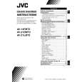
DISASSEMBLY PROCEDURE
REMOVING THE REAR COVER
1. Unplug the power plug. 2. As shown in figure, remove the
7
screws marked
!
and a
screw marked ". 3. Withdraw the rear cover toward you.
REMOVING THE MAIN PW BOARD
" After removing the rear cover. 1. Slightly raise the both sides of the MAIN PW BOARD by hand. 2. Withdraw the MAIN PW BOARD backward. (If necess ary, take off the wire clamp, c onnectors etc.)
REMOVING THE SPEAKER
" After removing the rear cover. 1. As shown in figure, remove the
2 screws marked # .
2. Follow the s ame steps when removing the other hand speak er.
CHECKING THE MAIN PW BOARD
1. To check the back side of the PW Board. 1) Pull out the MAIN PW Board. (Refer to REMOVING THE MAIN PW Board) 2) Erect the PW Board vertic ally so that you can easily check the back side of the PW Board. [CAUTION] " When erecting the PW Board, be careful s o that there will be no contacting with other PW Board. " Before turning on power, make sure that the CRT earth wire and other connector are properly c onnected.
WIRE CLAMPING AND CABLE TYING
1. Be sure to clamp the wire. 2. Never remove the c able tie used for tying the wires together. Should it be inadvertently removed, be sure to tie the wires with a new cable tie.
8
No. 52023
|
|
|
> |
|