|
|
|
Who's Online
There currently are 6043 guests online. |
|
Categories
|
|
Information
|
|
Featured Product
|
|
|
 |
|
|
There are currently no product reviews.
 ;
Impeccable, document très complet. Perfect, i get all i need. All schematic are correct. Thanks
;
The manual is of better quality compared to other. I found it less expensive and therefore it it is the best buy cost vs quality.
 ;
I bought the service-manual of the sony ICB-1020(an old transmitter-receiver) at "www.Owners-Manual.com", I found the service-manual for a fairly cheap price(in comparison with other sellers). I filled in some questions, payed the order with Ideal, and within 24 hours I had my service manual. I was very happy:In no time I had my service-manual and everything, but literally everything was noted down in the manual; the electronic scheme, the parts list, etcetera.
A very practical, reference-document.
;
This comprehesive service maual was greatly appreciated, as was the digital download.
;
Good en helpfull black and white scanned Srfvice manual of the Philps D8444. Quick service and delivery
AV-21L31 AV-25L31
REMOVING THE CRT
* Replacement of the CRT should be performed by 2 or more persons.
CRT CHANGE TABLE
� After removing the rear cover, chassis etc.,
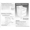
1. Putting the CRT change table on soft cloth, the CRT change table should also be covered with such soft cloth (shown in Fig. 2). 2. While keeping the surface of CRT down, mount the TV set on the CRT change table balanced will as shown in Fig. 3. 3. Remove 4 screws marked by arrows with a box type screwdriver as shown in Fig. 3. Since the cabinet will drop when screws have been removed, be sure to support the cabinet with hands. 4. After 4 screws have been removed, put the cabinet slowly on cloth (At this time, be carefully so as not to damage the front surface of the cabinet) shown in Fig. 4. The CRT should be assembled according to the opposite sequence of its dismounting steps.
APPROX. 35cm CLOTH
�
Fig. 2
�
CRT
* The CRT change table should preferably be smaller that the CRT surface, and its height be about 35cm.
CRT CHANGE TABLE BOX TYPE SCREW DRIVER
Fig. 3
CRT
COATING OF SILICON GREASE FOR ELECTRICAL INSULATION ON THE CRT ANODE CAP SECTION.
� Subsequent to replacement of the CRT and HV transformer or repair
of the anode cap, etc. by dismounting them, be sure to coat silicon grease for electrical insulation as shown in Fig. 5. 1. Wipe around the anode button with clean and dry cloth. (Fig. 5) 2. Coat silicon grease on the section around the anode button. At this time, take care so that any silicon greases does not sticks to the anode button. (Fig. 6) Silicon grease product No. KS - 650N
CABINET
CRT CHANGE TABLE
Fig. 4
CRT
Anode button
Approx. 20mm (Do not coat grease on this section
Silicon grease should be coated by 5mm or more from the outside diameter of anode cap.
Silicon grease coating
Anode button (No sticking of silicon grease)
Coating position of silicon grease Anode cap
Fig. 5
Fig. 6
8
No. 51908
|
|
|
> |
|