|
|
|
Who's Online
There currently are 5919 guests online. |
|
Categories
|
|
Information
|
|
Featured Product
|
|
|
 |
|
|
There are currently no product reviews.
 ;
This manual is very good. 303 pages scanned in a very high resolution. My camera has bad, leaking capacitors which all of the V5000 models are suffering from these days.
There is a huge part list with all capacitors, transistors etc. in this manual which helped me a lot. Otherwise I would not have been able to buy replacement parts.
The dissassembly guide is very enormous and detailed. Unlike on the Panasonic MS1 manual I downloaded here it actually looks like the real parts look. And the screws are labeled correctly, so you shouldn't have any left after the repair. ;)
;
has all the schematics you could need,and very well laid out format also has all part numbers along with an exploded view which is helpful
 ;
Very nice to have! Now it is no problem to understand how it is put together.
Helps me a lot.
;
good scans, all is clear. all pages in order. recommended
;
Très-très bon site, facile, très bon prix.
Au futur besoin, je n’hésiterais à faire appel à vous.
Merci
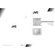
AV-21BD5EKI AV-21BD5EP AV-21BD5EE AV-21BD5EKIS AV-21BD5EPS AV-21BD5EES
ADJUSTMENTS
+B VOLTAGE CHECK
1. Receive the standard colour bar signal. 2. Connect digital voltmeter between + of B1 Line circuit and GND. 3. Confirm that voltage is DC 123V # 2.0V.
SCREEN
1. Set TV in AV mode without video signal � Black screen. 2. Set [WP Red], [WP Green] and [WP Blue] equal to �32�. 3. Set [Black R], [Black G] equal to �8�. 4. Set TV in normal I mode. 5. Adjust SCREEN VR (on FBT) such that the highest cathode cut-off voltage measured on CRT SOCKET PWB ASS�Y is DC 125V ± 5V.
WHITE BALANCE
NOTE : Confirm SCREEN Adjustment has been adjusted.
â� LOW LIGHT
1. 2. 3. 4. Input the 10-step gray scale signal. (include10% Black) Enter the SERVICE MODE. Turn the SCREEN VR (on FBT) gradually, to where the 2nd gray bar(10% Black) faintly visible. Adjust [Black B] and [Black R] not to the colours on the gray bar.
â� HIGH LIGHT
5. Apply the white signal. 6. Adjust [R DRIVE] and [G DRIVE] so that the picture becomes white.
FOCUS
1. Input the crosshatch pattern signal. 2. Adjust the FOCUS VR (on FBT) to have the best resolution on screen.
VERTICAL GEOMETRY
Adjust [V Amp], [V Shift] and [V Slope], [V Slope] [V S Cor] to compensate for vertical distortion.
HORIZONTAL PICTURE CENTERING
Adjust [H Shift] to have the picture in the center of the screen.
No.51742
1-11
|
|
|
> |
|