|
|
|
Who's Online
There currently are 5818 guests and
1 member online. |
|
Categories
|
|
Information
|
|
Featured Product
|
|
|
 |
|
|
There are currently no product reviews.
 ;
This is a high quality manual with clear schematic and components layout diagrams ; with service procedure included.
 ;
This service manual for the Kenwood KT-990D was reproduced really well ,is very legible and manual is complete.Combined with the low price paid,in the future,I will be checking Owner-Manuals.com any time I need a manual.
;
When I purchased this manual I had my doubts regarding the quality as the price was so reasonable as compared to other outlets.
The manual itself is of high standard the print is very clear as are the diagrams. Obviously with the diagrams one has to zoom in otherwise it is to small to be able to read.
Overall I am very pleased with the company who delivered as they said and with the manual they supplied.
I occasionally require a manual and now having registered with this company I shall order from them in the future.
;
I was at first dubious about payiong for downloaded manuals but having done so, I was extremely impressed with quality of the two manual I ordered, well worth the small price I paid.
I would highly recommend these to my friends.
;
reasonable price for the schematic - the service is perfect, all as expected and pointed by instructions - good scan of the original plans - thank you!
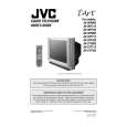
AV-27F703 AV-27F713 AV-27F803
SPECIFIC SERVICE INSTRUCTIONS
DISASSEMBLY PROCEDURE
REMOVING THE REAR COVER
1. Disc onnect the power plug from wall outlet. 2. As s hown in the Fig.1, remove the 12 screws marked !. 3. Withdraw the rear c over backward.
CHECKING THE CHASSIS
To check the PW Board from back side. 1. Pull out the chassis (refer to REMOVING THE CHASSIS). 2. Erect the chas sis vertically so that you c an easily check the back side of the PW Board.
REMOVING THE TERMINAL BOARD
" After removing the rear c over. 1. As s hown in Fig.1, remove the screws marked 2. Withdraw the terminal board toward you.
[CAUTION]
".
" When erecting the chassis, be careful so that there will be no contacting with other PW Board. " Before turning on power, make s ure that the wire connec tor is properly connec ted. " When conducting a check with power supplied, be sure to confirm that the CRT EARTH WIRE (BRAIDED ASS�Y) is connected to the CRT SOCKET PW boar d.
REMOVING THE CHASSIS
" After removing the rear c over / terminal board. 1. Slightly raise the both sides of chassis by hand and remove the
2 claws under the both side of the chassis from the front cabinet.
2. Withdraw the chass is backward. (If necess ary, remove the wire clamp, c onnectors etc.)
WIRE CLAMPING AND CABLE TYING
1. Be sure to clamp the wire. 2. Never remove the c able tie used for tying the wires together. Should it be inadvertently removed, be sure to tie the wires with a new cable tie.
REMOVING THE SPEAKER
" After removing the rear cover. 1. As shown in Fig. 1, removing the
4
screws marked
#,
then
remove the speaker. 2. Follow the s ame steps when removing the other hand speak er. NOTE : When removing the upper one.
4
screws mark ed
#
of the speaker,
remove the lower side screw first, and then remove the
REMOVING THE LED & POWER SW PWB
" After removing the rear c over & terminal board. 1. Remove the 2 screws marked $ as s hown in Fig.1. 2. Withdraw the LED & POWER SW PWB toward you. * If nec essary, remove the wire c lamp, connector etc.
REMOVING THE FRONT CONTROL PWB
" After removing the rear c over & terminal board. 1. Remove the 2 screws marked % as s hown in Fig.1. 2. Withdraw the FRONT CONTROL PWB toward you. * If nec essary, remove the wire c lamp, connector etc.
8
No.52005
|
|
|
> |
|