|
|
|
Who's Online
There currently are 5913 guests online. |
|
Categories
|
|
Information
|
|
Featured Product
|
|
|
 |
|
|
There are currently no product reviews.
 ;
everything i needed. it was easy to get. and this site is now my go to site for manuals.
 ;
Quality as promised it arrived fast. No problems what so ever
;
Good scan, very handy and it also includes the user manual. 122 pages in total.
;
This manual was exactly what I needed. Detailed, useful and delivered as promised.
;
Great manual good quality really helped in the repair of my Toshiba, thanks
AV-27F802
SPECIFIC SERVICE INSTRUCTIONS
DISASSEMBLY PROCEDURE
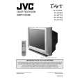
REMOVING THE REAR COVER
1. Unplug the power supply cord. 2. Remove the 12 screws marked A as shown in Fig.1. 3. Withdraw the REAR COVER toward you. [CAUTION]
REMOVING THE DAF PW BOARD
� After removing the rear cover and chassis.
1. Lift the right side of the DAF PWB while pressing the PWB stopper marked J and claw marked K in the arrow direction marked L as shown in Fig.1. 2. Then remove the DAF PWB. (If necessary, take off the wire, connector�s etc.)
� When reinstalling the rear cover, carefully push it inward after inserting the MAIN PWB into the rear cover groove.
REMOVING THE SPEAKER REMOVING THE CHASSIS
� After removing the rear cover.
1. Remove the 2 screws marked M as shown in Fig.1. 2. Withdraw the speaker backward. 3. Follow the same steps when removing the other hand speaker.
� After removing the rear cover.
1. Slightly raise the both sides of the chassis by hand and remove the 3 claws marked B under the chassis from the front cabinet as shown in Fig.1. 2. Withdraw the chassis backward along the rail in the arrow direction marked C as shown in Fig.1. (If necessary, take off the wire clamp, connector�s etc.)
CHECKING THE MAIN PW BOARD
1. To check the back side of the MAIN PW Board. 1) Pull out the chassis. (Refer to REMOVING THE CHASSIS). 2) Erect the chassis vertically so that you can easily check the back side of the MAIN PW Board. [CAUTION] When erecting the chassis, be careful so that there will be no contacting with other PW Board. other connectors are properly connected.
* When conducting a check with power supplied, be sure to confirm that the CRT earth wire is connected to the CRT SOCKET PWB and the MAIN PWB.
REMOVING THE TERMINAL BOARD
� After removing the rear cover.
1. Remove the 6 screws marked D as shown in Fig.1. 2. When you pull out the TERMINAL BOARD in the direction of arrow marked E as shown in Fig.1, it can be removed.
� � Before turning on power, make sure that the CRT earth wire and
WIRE CLAMPING AND CABLE TYING REMOVING THE FRONT AND POWER SW PW BOARDS
1. Be sure clamp the wire. 2. Never remove the cable tie used for tying the wires together. Should it be inadvertently removed, be sure to tie the wires with a new cable tie.
� After removing the rear cover and chassis.
1. Remove the 6 screws marked F as shown in Fig.1. 2. Then remove the FRONT PWB and POWER SW PWB. (If necessary, take off the wire, connector�s etc.)
REMOVING THE LF PW BOARD
� After removing the rear cover and chassis.
1. Lift the left side of the LF PWB while pressing the 2 PWB stoppers marked G in the arrow direction marked H as shown in Fig.1. 2. Then remove the LF PWB. (If necessary, take off the wire, connector�s etc.)
6
No. 51757
|
|
|
> |
|