|
|
|
Who's Online
There currently are 6041 guests and
2 members online. |
|
Categories
|
|
Information
|
|
Featured Product
|
|
|
 |
|
|
There are currently no product reviews.
 ;
factory technician level - complete with board views :
( removing chassis from cabinet , only thing missing ) ;
on weekends , staff is not available so - be patient .
;
Good complete Service-Manual (SONY PVM6041QM)
A few graphics and waveforms not very clear! (-1*)
 ;
Excellent manual. In addition to the information I needed was a complete description of both electronic and mechanical devices.
Excellent site.
Thank you very much.
;
very good and complete manual , it is in english and german is perfect for repair.
;
This manual is complete and of high quality. I am very pleased with the purchase.
AV28L2EUGR AV28L2EUBL AV28L2EUGY
REPLACEMENT OF CHIP COMPONENT
! CAUTIONS
1. 2. 3. 4. Avoid heating for more than 3 seconds. Do not rub the electrodes and the resist parts of the pattern. When removing a chip part, melt the solder adequately. Do not reuse a chip part after removing it.
! SOLDERING IRON
1. Use a high insulation soldering iron with a thin pointed end of it. 2. A 30w soldering iron is recommended for easily removing parts.
! REPLACEMENT STEPS
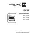
1. How to remove Chip parts # Resistors, capacitors, etc (1) As shown in the figure, push the part with tweezers and alternately melt the solder at each end.
2. How to install Chip parts
# Resistors, capacitors, etc (1) Apply solder to the pattern as indicated in the figure.
(2) Grasp the chip part with tweezers and place it on the solder. (2) Shift with tweezers and remove the chip part. Then heat and melt the solder at both ends of the chip part.
# Transistors, diodes, variable resistors, etc (1) Apply extra solder to each lead.
# Transistors, diodes, variable resistors, etc (1) Apply solder to the pattern as indicated in the figure. (2) Grasp the chip part with tweezers and place it on the solder. (3) First solder lead A as indicated in the figure.
SOLDER
SOLDER
(2) As shown in the figure, push the part with tweezers and alternately melt the solder at each lead. Shift and remove the chip part.
A B
C (4) Then solder leads B and C.
A B C
Note : After removing the part, remove remaining solder from the pattern.
No.51778
29
|
|
|
> |
|