|
|
|
Who's Online
There currently are 5842 guests online. |
|
Categories
|
|
Information
|
|
Featured Product
|
|
|
 |
|
|
There are currently no product reviews.
 ;
This was precisely what I was looking for. Complete and good quality!
 ;
This is the ONLY copy of this manual I could find for a realistic price. Even Panasonic could not provide me with one.
The PDF is a very good copy and it helped me diagnose and find the fault with the unit I have.
;
Very complete and well reading drawings. Documentation is essential for successful repairs.Good documentation, with all that is necessary. This manual was what I was waiting with all the information necessary for the repairing I need it for. You must buy it if you want to do repairs or simply understand how it works.
;
Excellent service manual includes everything is need to repair this radio-caseete, how to disassemble, wiring diagram, all , waiting time until the download was only a few hours. I'm going to buy service manuals from here, are cheap and very good.Thank you.
;
Good service manual,i saved from scrapping this deck,is now fully functional.Thanks.
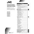
SECTION 3 DISASSEMBLY
3.1 DISASSEMBLY PROCEDURE 3.1.1 REMOVING THE TWIN PORT BASS BLASTER UNIT [AV-29VT31/P] � Unplug the power supply cord. (1) Disconnect the TWIN PORT BASS BLASTER UNIT's cord from the rear of the TV set. (2) Remove the TWIN PORT BASS BLASTER UNIT by pulling it upwards. NOTE: After removing the TWIN PORT BASS BLASTER UNIT, proceed to the following procedure. 3.1.2 REMOVING THE REAR COVER � Unplug the power cord. (1) Remove the 16 screws [A] as shown in Fig.1. (2) Withdraw the REAR COVER toward you. CAUTION: When reinstalling the rear cover, carefully push it inward after inserting the MAIN PWB into the REAR COVER groove. 3.1.3 REMOVING THE CHASSIS (CHASSIS BASE AND CONTROL BASE) � Remove the REAR COVER. (1) Slightly raise the both sides of the CHASSIS by hand and remove the 2 claws [B] under the CHASSIS from the front cabinet as shown in Fig.1. (2) Withdraw the CHASSIS backward. (If necessary, take off the wire clamp, connector's etc.) NOTE: When conducting a check with power supplied, be sure to confirm that the CRT earth wire is connected to the CRT SOCKET PWB and the MAIN PWB. 3.1.4 REMOVING THE AV TERMINAL BOARD � Remove the REAR COVER. (1) Remove the 4 screws [C] as shown in Fig.1. (2) When you pull out the AV TERMINAL BOARD in the direction of arrow [D] as shown in Fig.1, it can be removed. 3.1.5 REMOVING THE CONTROL BASE � Remove the REAR COVER. � Remove the CHASSIS. (1) While pushing down the 2 claws [E] as shown in Fig. 2 and pull out the CONTROL BASE in the direction of arrow [F] as shown in Fig. 2, the control base can be removed. (If necessary, take off the wire, connector's etc.) 3.1.6 REMOVING THE SPEAKER � Remove the REAR COVER. (1) Remove the 2 screws [G] as shown in Fig.1. (2) Withdraw the SPEAKER backward. (3) Follow the same steps when removing the other hand SPEAKER. 3.1.7 CHECKING THE MAIN PW BOARD � To check the back side of the MAIN PWB. (1) Pull out the CHASSIS. (Refer to REMOVING THE CHASSIS). (2) Erect the CHASSIS vertically so that you can easily check the back side of the MAIN PWB. CAUTIONS: � When erecting the chassis, be careful so that there will be no contacting with other PW Board. � Before turning on power, make sure that the CRT earth wire and other connectors are properly connected. � When repairing, connect the DEG. COIL to the DEG. connector on the MAIN PWB. 3.1.8 WIRE CLAMPING AND CABLE TYING (1) Be sure to clamp the wire. (2) Never remove the cable tie used for tying the wires together. Should it be inadvertently removed, be sure to tie the wires with a new cable tie.
(No. 52195) 1-7
|
|
|
> |
|