|
|
|
Who's Online
There currently are 5980 guests online. |
|
Categories
|
|
Information
|
|
Featured Product
|
|
|
 |
|
|
There are currently no product reviews.
 ;
There was no problem at all.After paying i had to wait only a few hours,than i could
download the manual in best pdf-quality.
Thank You !
 ;
I found this service manual to be complete in every detail except for troubleshooting charts. It would be helpful if it had a set of troubleshooting charts; however it is a very good manual otherwise and for the price it is very well worth it.
;
Complete manual included schematics layouts and alignment procedure, clear to read and magnify, extremely pleased with manual and owner manual . com's service
;
perfect, i am very satisfait for the réception of the sansui r-5l service manual, thank you very much
;
Thank you, this is a rare document. Few others have it, but they charge way more for a download.
Great deal (even if you have to wait a few hours to get it).
SECTION 3 DISASSEMBLY
3.1 DISASSEMBLY PROCEDURE 3.1.1 REMOVING THE REAR COVER � Unplug the power plug. (1) As shown in Fig.2, take out the 14 screws [A]. (2) Remove the REAR COVER toward you. NOTE : When reinstalling the REAR COVER, carefully push it inward after inserting the chassis into the REAR COVER groove. 3.1.6 REMOVING THE SPEAKER � Remove the REAR COVER. � Remove the CHASSIS BASE. (1) As shown in Fig.2, take out the 4 screws [H]. (2) Follow the same steps when removing the other hand SPEAKER. 3.1.7 CHECKING THE MAIN PW BOARD � To check the backside of the MAIN PWB. (1) Pull out the CHASSIS BASE. (Refer to REMOVING THE CHASSIS BASE). (2) Erect the chassis vertically so that you can easily check from the backside of the MAIN PWB. CAUTION : � When erecting the chassis, be careful so that there will be no contacting with other PWB. � Before turning on power, make sure that the CRT earth wire and other connectors are properly connected. 3.1.8 WIRE CLAMPING AND CABLE TYING (1) Be sure to clamp the wire. (2) Never remove the cable tie used for tying the wires together. Should it be inadvertently removed, be sure to tie the wires with a new cable tie.
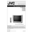
3.1.2 REMOVING THE CHASSIS BASE � Remove the REAR COVER. (1) Slightly raise the both sides of the CHASSIS BASE by hand, and teka out the 2 claws [B] (Fig.1 and Fig.2) under the both sides of the chassis from the chassis rail. (2) As shown in Fig.1, draw the CHASSIS BASE backward along the chassis rail [C] (Fig.1) in the arrow direction [D] (Fig.2). (If necessary, detach the wire clamp, connector's etc.) NOTE : When conducting a check with power supplied, be sure to confirm that the CRT earth wire is connected to the CRT SOCKET PWB and the MAIN PWB.
3.1.3 REMOVING THE TERMINAL BOARD � Remove the REAR COVER. (1) As shown in Fig.2, take out the 4 screws [E]. (2) When you pull out the TERMINAL BOARD, it can be removed.
FRONT CABINET
3.1.4 REMOVING THE FRONT CONTROL PW BOARD � Remove the REAR COVER. � Remove the CHASSIS BASE. (1) As shown in Fig.2, take out the 3 screws [F] attached the FRONT CONTROL PWB with the front cabinet. (2) Then remove the FRONT CONTROL PWB.
MAIN PWB
C
3.1.5 REMOVING THE FRONT TERMINAL PW BOARD � Remove the REAR COVER. � Remove the CHASSIS BASE. (1) As shown in Fig.2, take out the 2 screws [G]. (2) Then remove the FRONT TERMINAL PWB.
CHASSIS BASE
B
Fig.1
(No.52121)1-9
|
|
|
> |
|