|
|
|
Who's Online
There currently are 6022 guests online. |
|
Categories
|
|
Information
|
|
Featured Product
|
|
|
 |
|
|
There are currently no product reviews.
 ;
very helpful, I could not have cleaned motherboard and replaced the main fan without it
 ;
Good manual, schematics nice and clear with good quality scanning. Woul dhave been nice to have immediate access after purchasing though.
;
I was very glad recieving the service manal from You. Manuals were delivered promptly and were correct as advertised. A complete and very usefull service manual with all details. Thank you!
;
Very clear copy. No pages missing. Big bonus is that it includes supplement. Price is affordable compared to what others ask for.
;
Found the quality of the copy excellent and a very quick service. I would certainly recommend the service.
AV-36360 AV-36S36 AV-36330 AV-36S33 AV-36320
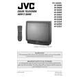
REPLACEMENT OF CHIP COMPONENT
! CAUTIONS
1. 2. 3. 4. Avoid heating for more than 3 seconds. Do not rub the electrodes and the resist parts of the pattern. When removing a c hip part, melt the s older adequately. Do not reuse a chip part after removing it.
! SOLDERING IRON
1. Use a high ins ulation s oldering iron with a thin pointed end of it. 2. A 30w s oldering iron is rec ommended for easily removing parts.
! REPLACEMENT STEPS
1. How to remove Chip parts # Resistors, capacitors, etc (1) As shown in the figure, push the part with tweezers and alternately melt the solder at each end.
2. How to install Chip parts
# Resistors, capacitors, etc (1) Apply solder to the pattern as indic ated in the figure.
(2) Shift with tweezers and remove the chip part.
(2) Grasp the chip part with tweezers and plac e it on the s older. Then heat and melt the solder at both ends of the chip part.
# Transistors, diodes, variable r esistor s, etc (1) Apply extra solder to each lead.
# Transistors, diodes, variable r esistor s, etc (1) Apply solder to the pattern as indic ated in the figure. (2) Grasp the chip part with tweezers and place it on the solder. (3) First s older lead A as indicated in the figure.
SOLD E R
SOLD E R
A (2) As shown in the figure, push the part with tweezers and alternately melt the solder at each lead. Shift and remove the chip part. B C (4) Then solder leads B and C.
A B Note : After removing the part, remove remaining solder from the pattern. C
No.51950
13
|
|
|
> |
|