|
|
|
Who's Online
There currently are 5986 guests online. |
|
Categories
|
|
Information
|
|
Featured Product
|
|
|
 |
|
|
There are currently no product reviews.
 ;
Good pdf of the service manual for this unit. Includes disassembly instructions, full schematics, board layouts, parts lists and diagnostic information. Some information is in the pdf twice (single pages, and split pages), but that could be how it was originally generated by panasonic, or perhaps the idea is to make it eaiser to put onto 8.5 x 11" pages.
Information was exactly what I needed. Delivery was overnight (less than 12 hours) and I was happy with the process.
;
5 STARS for FAST DELIVERY, BEST PRICES and QUALITY PRODUCT. Item was exactly as described with superb resolution. Will definitely source all my future requirements from this website. Thanks a lot owner-manual.com!
;
OEM manual provided all schematics, board layouts and component specs necessary to facilitate unit maintenance. All pages were clear and readable.
;
Good condition and quality. Hard to find anywhere in Internet, only on this site.
 ;
Exactly what I needed to be able to bring the amp back to life... will come back to this site the next time I need schematics.
AV-36360 AV-36S36 AV-36330 AV-36S33 AV-36320
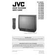
REPLACEMENT OF CHIP COMPONENT
! CAUTIONS
1. 2. 3. 4. Avoid heating for more than 3 seconds. Do not rub the electrodes and the resist parts of the pattern. When removing a c hip part, melt the s older adequately. Do not reuse a chip part after removing it.
! SOLDERING IRON
1. Use a high ins ulation s oldering iron with a thin pointed end of it. 2. A 30w s oldering iron is rec ommended for easily removing parts.
! REPLACEMENT STEPS
1. How to remove Chip parts # Resistors, capacitors, etc (1) As shown in the figure, push the part with tweezers and alternately melt the solder at each end.
2. How to install Chip parts
# Resistors, capacitors, etc (1) Apply solder to the pattern as indic ated in the figure.
(2) Shift with tweezers and remove the chip part.
(2) Grasp the chip part with tweezers and plac e it on the s older. Then heat and melt the solder at both ends of the chip part.
# Transistors, diodes, variable r esistor s, etc (1) Apply extra solder to each lead.
# Transistors, diodes, variable r esistor s, etc (1) Apply solder to the pattern as indic ated in the figure. (2) Grasp the chip part with tweezers and place it on the solder. (3) First s older lead A as indicated in the figure.
SOLD E R
SOLD E R
A (2) As shown in the figure, push the part with tweezers and alternately melt the solder at each lead. Shift and remove the chip part. B C (4) Then solder leads B and C.
A B Note : After removing the part, remove remaining solder from the pattern. C
No.51950
13
|
|
|
> |
|