|
|
|
Who's Online
There currently are 5822 guests online. |
|
Categories
|
|
Information
|
|
Featured Product
|
|
|
 |
|
|
There are currently no product reviews.
 ;
Il service manual molto accurato. Rapidi nella risposta
;
Quick site processing. A complete and very useful manual with all details. Thank you!
;
Quick service response. A useful and very rare service manual with all details. I recomend this service.
;
I ordered this manual sometime in the afternoon and I received it on my e-mail the same evening.
This is a fantastically good and properly scanned copy of the original manual. All pages are of the same scale and they overlap each other. It means that you can print the manual and easily make it as a convenient paper manual.
The content of the manual is fantastic. Alignment descriptions, PCB layouts and elementary diagrams are explicit and precise. I immediately found what I was looking for. Thanks to this manual and Owner-Manuals.com my amplifier is alive again. Many thanx indded!
;
The manual was well-scanned and easy to read. As an added bonus, the Operator's Manual was bundled with the Service Manual!
I'd definitely use owner-manuals.com again.
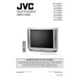
AV-36D202 AV-36D302 AV-36D502
SPECIFIC SERVICE INSTRUCTIONS
DISASSEMBLY PROCEDURE
REMOVING THE REAR COVER
1. Unplug the power supply cord. 2. Remove the 12 screws marked A as shown in Fig.1. 3. Withdraw the REAR COVER toward you. [CAUTION] When reinstalling the rear cover, carefully push it inward after inserting the MAIN PWB into the rear cover groove.
REMOVING THE SPEAKER
� After removing the rear cover.
1. Remove the 4 screws marked H as shown in Fig.1. 2. Withdraw the speaker backward. 3. Follow the same steps when removing the other hand speaker.
�
CHECKING THE MAIN PW BOARD REMOVING THE CHASSIS
1. To check the back side of the MAIN PW Board. 1) Pull out the chassis. (Refer to REMOVING THE CHASSIS). 2) Erect the chassis vertically so that you can easily check the back side of the MAIN PW Board. [CAUTION] When erecting the chassis, be careful so that there will be no contacting with other PW Board. Before turning on power, make sure that the CRT earth wire and other connectors are properly connected.
� After removing the rear cover.
1. Slightly raise the both sides of the chassis by hand and remove the 3 claws marked B under the chassis from the front cabinet as shown in Fig.1. 2. Withdraw the chassis backward along the rail in the arrow direction marked C as shown in Fig.1. (If necessary, take off the wire clamp, connector�s etc.)
� �
* When conducting a check with power supplied, be sure to confirm
that the CRT earth wire is connected to the CRT SOCKET PWB and the MAIN PWB.
WIRE CLAMPING AND CABLE TYING
1. Be sure clamp the wire. 2. Never remove the cable tie used for tying the wires together. Should it be inadvertently removed, be sure to tie the wires with a new cable tie.
REMOVING THE TERMINAL BOARD
� After removing the rear cover.
1. Remove the 4 screws marked D as shown in Fig.1. 2. When you pull out the TERMINAL BOARD in the direction of arrow marked E as shown in Fig.1, it can be removed.
REMOVING THE FRONT CONTROL AND FRONT AV INPUT PW BOARDS
� After removing the rear cover and chassis.
1. Remove the 3 screws marked F and the 2 screws marked G as shown in Fig.1. 2. Then remove the FRONT CONTROL PWB and FRONT AV INPUT PWB. (If necessary, take off the wire, connector�s etc.)
8
No. 51798C
|
|
|
> |
|