|
|
|
Who's Online
There currently are 5942 guests online. |
|
Categories
|
|
Information
|
|
Featured Product
|
|
|
 |
|
|
There are currently no product reviews.
 ;
This service manual helped me to repair my PIONEER. Iam very satisfied, that I found it here.
Even the price of manual was not so high that person would not be able to spend a few money.
But that is very worth spent money. Thanks
 ;
Excellent quality service manual. Quick processing, fair prices. Love to do business again. Thank you!!!
;
Excellent service manual, the only known point of note is the alignment of improvability scanned pages within the pdf page. The resolution is good.
;
I was very glad recieving the service manal from You. Additionaly very fast. Extremaly nice servicing. Thanks very mach! Now my GX-220 working better, than it was made. Alexander from Moscow, Russia/
;
Sweet! I won the item on eBay and couldn't adjust the geometry or even keep a steady picure. This guide has the full schematics (not available anywhere else as far as I could tell), and was a bargain for the wealth of knowledge it contains. I hooked it up to my testing equipment, tweaked a few potentiometers and got it playing videogames in no time. Thanks!
3.3
MEMORY IC REPLACEMENT
3.3.1 MEMORY IC This TV uses memory IC. This memory IC stores data for proper operation of the video and deflection circuits. When replacing the memory IC, be sure to use an IC containing this (initial value) data. 3.3.2 MEMORY IC REPLACEMENT PROCEDURE 1. Power off Switch off the power and disconnect the power cord from the wall outlet. 2. Replace the memory IC Be sure to use a memory IC written with the initial setting data. 3. Power on Connect the power cord to the wall outlet and switch on the power. 4. Confirm the system constant value � 12.SYSTEM (SYS) do not adjust normally. � The adjustment should not be done without signal. How to enter the SERVICE MENU. � Confirm that the setting of TV/CATV SW is at the "TV" side and the setting of VCR/DVD SW is at the "VCR" side. (1) Before disappear the display of SLEEP TIMER settings, simultaneously press the [DISPLAY] key and [VIDEO STATUS] key of the remote control unit. (2) The SERVICE MENU screen will be displayed as shown Fig.1. How to enter the 12. SYSTEM(SYS). (1) While the SERVICE MENU is displayed, select 12.SYSTEM(SYS) item with [CH / ] keys, and [VOL / ] keys is pressed, the screen will displayed as shown in Fig.2. (2) Refer to the "12.SYSTEM(SYS)" table and check the the be the
SYS01 VIDEO IN Fig.2 SERVICE MENU SERVICE MENU
1. V/C(S)
3. SOUND(A) 7. LOW LIGHT 9. RF AFC 11. I2C BUS
2. DEF(D)
4. OTHERS(F) 6. 3L Y/C(LYC) 8. HIGH LIGHT 10. VOC 12. SYSTEM(SYS)
SELECT BY OPERATE BY Fig.1
EXIT BY EXIT
12.SYSTEM (SYS)
setting items. If the value is different, select the setting item with the [CH / ] keys and adjust the setting with the [VOL / ] keys. (The letters of the selected item are displayed in yellow.) (3) When adjustment has completed, the values store into memory IC automatically. (4) Press the [EXIT] key to return the SERVICE MENU screen. (5) Then press the [EXIT] key again to return the normal screen. 5. Receiving channel setting Refer to the OPERATING INSTRUCTIONS (USER'S GUIDE) and set the receive channels (Channels Preset) as described. 6. User settings Check the user setting items according to the "FACTORY SETTING ITEM" table. Where these do not agree, refer to the OPERATING INSTRUCTIONS (USER'S GUIDE) and set the items as described. 7. SERVICE MENU setting Verify what to set in the SERVICE MENU, and set whatever is necessary(Fig.1) . Refer to the SERVICE ADJUSTMENT for setting.
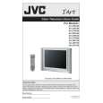
KEY ASSIGNMENT OF REMOTE CONTROL UNIT
SLEEP TIMER key
DISPLAY & VIDEO STATUS key
SOUND
V.STATUS
ASPECT
LIGHT
C.C.
VOL
/ key
CH
/
key EXIT key
[RM-C1251G]
1-12 (No.52114)
|
|
|
> |
|