|
|
|
Who's Online
There currently are 5902 guests online. |
|
Categories
|
|
Information
|
|
Featured Product
|
|
|
 |
|
|
There are currently no product reviews.
 ;
Very clear copy. No pages missing. Big bonus is that it includes supplement. Price is affordable compared to what others ask for.
;
Found the quality of the copy excellent and a very quick service. I would certainly recommend the service.
;
Good quality, clear diagrams. Exactly what I needed.
 ;
Good product. All the information is invcluded, but due to the complexity of the amplifier, it still is difficult to get it to operation again.
;
Very professional seller; very fast, accurate and rielable service.
3.3
REPLACEMENT OF CHIP COMPONENT
3.3.1 CAUTIONS (1) Avoid heating for more than 3 seconds. (2) Do not rub the electrodes and the resist parts of the pattern. (3) When removing a chip part, melt the solder adequately. (4) Do not reuse a chip part after removing it. 3.3.2 SOLDERING IRON (1) Use a high insulation soldering iron with a thin pointed end of it. (2) A 30w soldering iron is recommended for easily removing parts. 3.3.3 REPLACEMENT STEPS 1. How to remove Chip parts [Resistors, capacitors, etc.] (1) As shown in the figure, push the part with tweezers and alternately melt the solder at each end.
2. How to install Chip parts [Resistors, capacitors, etc.] (1) Apply solder to the pattern as indicated in the figure.
(2) Shift with the tweezers and remove the chip part.
(2) Grasp the chip part with tweezers and place it on the solder. Then heat and melt the solder at both ends of the chip part.
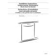
[Transistors, diodes, variable resistors, etc.] (1) Apply extra solder to each lead.
[Transistors, diodes, variable resistors, etc.] (1) Apply solder to the pattern as indicated in the figure. (2) Grasp the chip part with tweezers and place it on the solder. (3) First solder lead A as indicated in the figure.
SOLDER
SOLDER
(2) As shown in the figure, push the part with tweezers and alternately melt the solder at each lead. Shift and remove the chip part.
A B C
(4) Then solder leads B and C.
A
NOTE : After removing the part, remove remaining solder from the pattern.
B C
1-10 (No.YA052)
|
|
|
> |
|