|
|
|
Who's Online
There currently are 5953 guests online. |
|
Categories
|
|
Information
|
|
Featured Product
|
|
|
 |
|
|
There are currently no product reviews.
 ;
Excellent printing quality.
A complete and very usefull service manual with all details.
GREAT SERVICE AT VERY LOW PRICE!
A++
;
Excellent printing quality.
A complete and very usefull service manual with all details.
GREAT SERVICE AT VERY LOW PRICE!
A++
;
Excellent printing quality.
A complete and very usefull service manual with all details.
GREAT SERVICE AT VERY LOW PRICE!
A+
;
Excellent printing quality.
A complete and very usefull service manual with all details.
GREAT SERVICE AT VERY LOW PRICE!
A++
;
Best help everywhere i got from here. My audio medicinman was happy to get this manual from me. So he could repair my pioneer perfectly. Thanks
R O
AV-N29302
REPLACEMENT OF CHIP COMPONENT
! CAUTIONS
1. 2. 3. 4. Avoid heating for more than 3 seconds. Do not rub the electrodes and the resist parts of the pattern. When removing a chip part, melt the solder adequately. Do not reuse a chip part after removing it.
! SOLDERING IRON
1. Use a high insulation soldering iron with a thin pointed end of it. 2. A 30w soldering iron is recommended for easily removing parts.
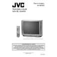
! REPLACEMENT STEPS
1. How to remove Chip parts # Resistors, capacitors, etc. (1) As shown in the figure, push the part with tweezers and alternately melt the solder at each end.
2. How to install Chip parts
# Resistors, capacitors, etc. (1) Apply solder to the pattern as indicated in the figure.
(2) Grasp the chip part with tweezers and place it on the solder. Then heat and melt the solder at both ends of the (2) Shift with tweezers and remove the chip part. chip part.
# Transistors, diodes, variable resistors, etc. (1) Apply extra solder to each lead.
# Transistors, diodes, variable resistors, etc. (1) Apply solder to the pattern as indicated in the figure. (2) Grasp the chip part with tweezers and place it on the solder. (3) First solder lead A as indicated in the figure.
SOLDER
SOLDER
(2) As shown in the figure, push the part with tweezers and alternately melt the solder at each lead. Shift and remove the chip part.
A B
C (4) Then solder leads B and C.
A B Note : After removing the part, remove remaining solder from the pattern. C
28
No. 51834
|
|
|
> |
|