|
|
|
Who's Online
There currently are 5691 guests online. |
|
Categories
|
|
Information
|
|
Featured Product
|
|
|
 |
|
|
There are currently no product reviews.
 ;
Excellent manual, detailed, very useful! Exactly what I needed, I'd recommend it to all who need it. Although images are scanned easily readable and explicit. A valuable tool product at a price more than modest, take it with confidence and you will not regret it!
;
Clear and complete service manual. Easy now to restore my old Kenwood KD-1500.
Thanks a lot.
;
Thanks for this "hard to find" service manual. This Sony PS212A is a very good turntable that needed to be restored !
 ;
Excellent quality on these manuals. Same as having the original printed manual and incredibly useful when doing a custom install like me. Keep it up on the good work.
;
This is an excellent information source. Great quality and tons of info regarding technical service for the Technics SH8065.
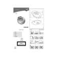
AV-N29304 AV-N29430 2.5 DISASSEMBLY PROCEDURE 2.5.1 (1) (2) (3) (4) 2.5.2 (1) (2) (3) (4) REMOVING THE REAR COVER [AV-N29304] Unplug the power plug. Remove the 11 screws [A] (Fig.1). Remove the 4 screws [B] (Fig.1). Then remove the REAR COVER toward you. REMOVING THE REAR COVER [AV-N29430] Unplug the power plug. Remove the 7 screws [A] (Fig.2). Remove the 4 screws [B] (Fig.2). Then remove the REAR COVER toward you. 2.5.6 CHECKING THE PW BOARD (1) Pull out the MAIN PWB (refer to REMOVING THE MAIN PWB). (2) Erect the MAIN PWB vertically so that you can easily check the backside of the PW Board. CAUTION: � When erecting the chassis, be careful so that there will be no contacting with other PW Board. � Before turning on power, make sure that the wire connector is properly connected. � When conducting a check with power supplied, be sure to confirm that the CRT EARTH WIRE (BRAIDED ASS'Y) is connected to the CRT SOCKET PW board. 2.5.7 WIRE CLAMPING AND CABLE TYING (1) Be sure to clamp the wire. (2) Never remove the cable tie used for tying the wires together. Should it be inadvertently removed, be sure to tie the wires with a new cable tie.
2.5.3 REMOVING THE MAIN PWB � Remove the REAR COVER. (1) Raise this side of the MAIN PWB, and remove the PWB STOPPER [C] from the cabinet. (2) Withdraw the MAIN PWB backward. (If necessary, remove the wire clamp, connectors etc.)
2.5.4 REMOVING THE SPEAKER [AV-N29304] � Remove the REAR COVER. (1) Remove the 4 screws [D], then remove the speaker (Fig.1). (2) Follow the same steps when remove the other hand speaker.
2.5.5 REMOVING THE SPEAKER [AV-N29430] � Remove the REAR COVER. (1) Remove the 4 screws [D], then remove the speaker (Fig.2). (2) Follow the same steps when remove the other hand speaker. NOTE: When removing the 4 screws [D] of the speaker, remove the lower side screw first, and then remove the upper one.
1-6 (No.52129)
|
|
|
> |
|