|
|
|
Who's Online
There currently are 5697 guests online. |
|
Categories
|
|
Information
|
|
Featured Product
|
|
|
 |
|
|
There are currently no product reviews.
 ;
Perfect manual, perfect service. Easy reading. Thanks a lot
;
Very good quality download here. Great hard to find manuals at a reasonable price.
 ;
I had a problem with the mains transformer, I did not know the voltages on the secondary, this manual helped me to solve this problem, thanks for the manual!
;
Great manual, great quality copy, complete parts reference and scematics, Thank you
;
Very good as always. Also this manual appears clear and well processed. I know it will help me to work on this TV. Thank you a lot! Matteo
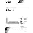
DVD mechanism assembly and parts list
B lo ck N o . M 2 M M
CLAMPER SA
NOTES: 1.Attach the MAGNET to the CLAMPER. 2.Lock the MAGNET and BACK YORK to the CLAMPER firmly with its 3 hooks. 3.Make sure that none of the 3 hooks of the CLAMPER is broken/ bent/ changed in shape.
31 31 30
29 28 27
3 hooks
CLAMPER SA
[FIG-1] LOADING MOTOR - PULLEY Press Fitting.
MOTOR PULLEY Height should be 5.35 -0.4
-0.1
1
26
26
TOP COVER Back
(Measurement between the top part of the PULLEY
6 23 24 22
and the top of the MOTOR Can)
-0.1 5.35-0.4
5
[FIG-2] INSULATOR Attachment NOTES:
1.Insert the INSULATOR firmly without mixing up the top and bottom side. 2.After the attachment of the INSULATOR, fasten the LOADER SCREW. 3.Be sure that the LOADER SCREW is not fastened at an angle of improperly fastened.
LOWER CASE LOADER SCREW INSULATOR LOADER BKT
25
DRAWING FROM DIRECTION A
DRAWING FROM DIRECTION B
21 3
21 20 3 3 21
[FIG-3] LOWER CASE/ SLIDER Grease Application Point
SLIDER: 6 Grease Application Points Type of Grease: TAG- 200R Amount of Grease: 8 1mg each NOTES: 1.After the attachment of the SLIDER to the LOWER CASE, pull the SLIDER towards the SNAPFIT (left side). Apply the grease to the points shown in the figure below. 2.Grease should be applied before the attachment of TRAVERSE BASE SA. LOWER CASE
2
We cannot supply parts that are not in the Parts List, as they are not exchangeable because of the design feature. Please handle the replacement with Mechanism Assembly Units.
17 15 8 17
1 10 9 11
7 14
LOWER CASE SLIDER Grease Application Points
13 6 17 12
cb
8
19 8
Back
"a" LOWER CASE: 9 Grease Application Points Type of Grease: TAG- 200R Amount of Grease: 8 1mg each Note: Application amount at area "a" (left of PULLEY GEAR SHAFT) is 64 4mg. NOTES: 3.Apply Grease in the center of GEAR Attaching SHAFT. 4.Apply Grease before attaching any kind of GEARS.
19 5 4
8
[FIG-3] GEAR Attachment NOTES:
18
10
Correct Phase Adjustment
Each Phase Adjustment Mark is on the straight line.
1.Attachment order of the GEARS is as follows, [GEAR 2] [GEAR 3] [GEAR 1] [PULLEY GEAR]. Be sure to adjust the Phase of GEAR 2 and GEAR 3.
NOTES: <GEAR 2 Phase Mark> <GEAR 3 Phase Mark> Make mark as a Phase Adjustment Mark
16
Make the salient of the outer circumference of GEAR 3 as a Phase Adjustment Mark.
9
3-4(No.XA019)
|
|
|
> |
|