|
|
|
Who's Online
There currently are 5874 guests online. |
|
Categories
|
|
Information
|
|
Featured Product
|
|
|
 |
|
|
There are currently no product reviews.
 ;
Good morning, the service manual you sent me was perfect.
Your service and answering are excellent.
I recomend this service.
Best regards.
 ;
I had been looking everywhere for a proper service manual for this VCR. Everywhere else that has this available for download has a very light version. This is the full service manual with all aspects that would interest anyone looking for the service manual for the AIWA HV-MX100 Worldwide VHS VCR. Great quality (as always). A winner hands down. Best Quality.
;
Top quality manual. Covers all aspects you'd expect in a top quality service manual for this Panasonic VHS VCR. The manual resolution is high. Another top quality manual from the only site worth downloading manuals from! If you're looking for a manual for the PV-9662 VHS VCR, this is the one you'll want to get!
;
complete part-lists and pcb layout, schematic diagram is good enlargable,
;
Excellent, fast delivery, excellent product. Good luck!
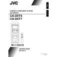
3.1.9 Removing the amplifier 1 and amplifier 2 boards (See Fig.17 to 19) [For DX-T9] � Remove the metal cover, tuner, fan, rear panel and main board. (1) (1)From the right side of the main body, remove the screw N attaching the earth wires to the bottom chassis. (See Fig.17.) Reference: After reassembling, fix the earth wires with the spacer as before. (See Fig.17.) (2) Disconnect the amplifier 2 board from the bridge board in the direction of the arrow while releasing the claw j of the connector CN200 on the bridge board. (See Fig.17.) (3) (3)From the left side of the main body, disconnect the card wire from the connector CN303 on the amplifier 1 board. (See Fig.17.) (4) Disconnect the amplifier 1 board from the bridge board in the direction of the arrow while releasing the claw k of the connector CN201 on the bridge board. (See Fig.18.) Note: When releasing the claws (j, k), take care not to break them. (See Figs.17 and 18.) Take out the amplifier 1 board and amplifier 2 board together from the main body. Remove the two screws P and remove the leaf spring. (See Fig.19.) Remove the two screws P and remove the amplifier 1 board from the heat sink. (See Fig.19.) Remove the four screws P and remove the amplifier 2 board from the heat sink. (See Fig.19.)
3.1.11 Removing the amplifier 1 and amplifier 2 boards (See Fig.17 to 19) [For DX-T5] � Remove the metal cover, tuner, fan, rear panel and main board. (1) From the right side of the main body, remove the screw N attaching the earth wires to the bottom chassis. (See Fig.17.) Reference: After reassembling, fix the earth wires with the spacer as before. (See Fig.17.) (2) Disconnect the amplifier 2 board from the bridge board in the direction of the arrow while releasing the claw j of the connector CN200 on the bridge board. (See Fig.17.) (3) From the left side of the main body, disconnect the card wire from the connector CN303 on the amplifier 1 board. (See Fig.17.) (4) Disconnect the amplifier 1 board from the bridge board in the direction of the arrow while releasing the claw k of the connector CN201 on the bridge board. (See Fig.18.) Note: When releasing the claws (j, k), take care not to break them. (See Figs.17 and 18.) (5) Take out the amplifier 1 board and amplifier 2 board together from the main body. (6) Remove the two screws P attaching the leaf spring and remove the amplifier 1 board from the heat sink. (See Fig.19.) (7) Remove the two screws P and remove the amplifier 2 board from the heat sink. (See Fig.19.)
(5) (6) (7) (8)
3.1.10 Removing the amplifier 1 and amplifier 2 boards (See Fig.17 to 19) [For DX-T7] � Remove the metal cover, tuner, fan, rear panel and main board. (1) From the right side of the main body, remove the screw N attaching the earth wires to the bottom chassis. (See Fig.17.) Reference: After reassembling, fix the earth wires with the spacer as before. (See Fig.17.) (2) Disconnect the amplifier 2 board from the bridge board in the direction of the arrow while releasing the claw j of the connector CN200 on the bridge board. (See Fig.17.) (3) From the left side of the main body, disconnect the card wire from the connector CN603 on the amplifier 1 board. (See Fig.17.) (4) Disconnect the amplifier 1 board from the bridge board in the direction of the arrow while releasing the claw k of the connector CN201 on the bridge board. (See Fig.18.) Note: When releasing the claws (j, k), take care not to break them. (See Figs.17 and 18.) Take out the amplifier 1 board and amplifier 2 board together from the main body. Remove the two screws P and remove the leaf spring. (See Fig.19.) Remove the two screws P and remove the amplifier 1 board from the heat sink. (See Fig.19.) Remove the three screws P and remove the amplifier 2 board from the heat sink. (See Fig.19.)
(5) (6) (7) (8)
1-18 (No.MB368)
 $4.99 DX-T5 JVC
Owner's Manual Complete owner's manual in digital format. The manual will be available for download as PDF file aft…
|
|
|
> |
|