|
|
|
Who's Online
There currently are 5783 guests online. |
|
Categories
|
|
Information
|
|
Featured Product
|
|
|
 |
|
|
There are currently no product reviews.
 ;
MACKIE HR824 26 pages English-only Service Manual contains:
1) HR824 technical overview with the description of front and rear panel switches.
2) HR824 specs
3) Block Diagram
4) Wiring Diagram
5) Packaging management
6) Spare part & final assembly list (for PCB rev A and B) + exploded view
7) Test Procedures (where, how to measure voltage...) including Test Point diagram on the PCB.
8) IC and Transistor charts.
Excellent guide: very clear, good scan quality enabling us to print readable diagram :-)
Note:
Mackie HR824 make extensive use of surface mount devices (SMD). Service on the HR824 must
only be undertaken by experienced service technicians with the right tools, experience and patience to perform surface mount rework when needed.
;
This Service manual is very well scanned and its clean to read, no any anti-theft words that un-english could understand. I got my CCD600 working with this manual and it´s clear shematics :)
;
I was very pleased with the service provided and was surprised at how good the quality was of the manual. I thought it may be a third generation copy or so, but it is as good as the websites that charge 3 times this much. I repair some electronics for family and friends without charge, so this is perfect for me. Thank you very much.
;
The service was great and the document was also great. Highly recommend!!!!
If anyone has a users manual... Please email me. need one. $ [email protected]
;
I needed a service manual as the display on my oscilloscope was very dim. I thought I'd give owner-manuals.com a try, as they advertised a huge number of manuals. Sure enough they had one listed. I bought it hoping it would be useful... actually, I bought it hoping it would be readable! I've had manuals from online sources in the past, and been very disappointed. Not this time! An excellent manual, complete, and very readable. Using it I fixed my 'scope, and as such the manual was an investment that paid off manyfold. Do I have any complaints? One very minor one - The circuit diagrams could have been scanned at a higher resolution, as some of the details were a little difficult to make out - not impossible, just not as easy as my old eyes would like! Overall, I'm very satisfied with my manual, and I will certainly be using this company again. Well done.
5.2
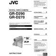
EMERGENCY DISPLAY
Example (in case of the error number E01):
E01 E01 REMOVE AND REATTACH BATTERY
Whenever some abnormal signal is input to the syscon CPU, an error number (E01, as an example) is displayed on the LCD monitor or (in the electronic view finder).In every error status, such the message as shown below alter nately appear over and over. � In an emergency mode, all operations except turning on/off the POWER switch are ineffectual. LCD display E01 Emergencymode LOADING Details
UNIT IN
SAFEGUARD MODE
Possible cause
In the case the encoder position is 1. The mechanism is locked during mode shift. not shifted to the next point though 2. The mechanism is locked at the mechanism loading end, the loading motor has rotated in the because the encoder position is skipped during loading direction for 4 seconds or mechanism mode shift. more. This error is defined as [E01]. 3. No power is supplied to the loading MDA. In the case the encoder position is 1. The mechanism is locked during mode shift. not shifted to the next point though 2. The mechanism is locked at the mechanism loading end, the loading motor has rotated in the because the encoder position is skipped during unloading direction for 4 seconds or mechanism mode shift. more. This error is defined as [E02]. 1. The idler gear does not engage with the reel disk well. 2. Though the idler gear and reel disk are engaged with each other, the tape is not wound because of overload to the mechanism. 3. No FG pulse is output from the reel sensor. 4. No power is supplied to the reel sensor. 5. Tape transport operation takes place with a cassette having no tape inside. 6. The tape slackens and no pulse is produced until the slack is taken up and the tape comes into the normal status.
E02
UNLOADING
E03
TU & SUP REEL FG In the case no REEL FG is produced for seconds shown in the table below or more in the capstan rotation mode after loading was complete, the mechanism mode is shifted to STOP with the pinch roller set off. This error is defined as [E03].However, no REEL EMG is detected in the SLW/STILL mode.
REEL(SUP) REEL(TU) PB/REC 3 SEC 3 SEC S-FWD 3 SEC 0.3 SEC S-REW 0.3 SEC 3 SEC FF 3 SEC 0.1 SEC REW 0.1 SEC 3 SEC
E04
DRUM FG
In the case there is no DRUM FG 1. The drum cannot be started or drum rotation is stopped input in the drum rotation mode for because tape transport load is too high. 4 seconds or more. This error is 1) Tape tension is extremely high. defined as [E04], and the 2) The tape is damaged or soiled with grease, etc. mechanism mode is shifted to 2. The DRUM FG signal is not received by the syscon CPU. STOP with the pinch roller set off. 1) Disconnection in the middle of the signal line. 2) Failure of the DRUM FG pulse generator (hall element). 3. No drum control voltage is supplied to the MDA. 4. No power is supplied to the DRUM MDA. In the case no CAPSTAN FG is 1. The CAPSTAN FG signal is not received by the syscon produced in the capstan rotation CPU. mode for 2 seconds or more. This 1) Disconnection in the middle of the signal line. error is defined as [E06], and the 2) Failure of the CAPSTAN FG pulse generator (MR mechanism mode is shifted to element). STOP with the pinch roller set 2. No capstan control voltage is supplied to the MDA. off.However, no CAPSTAN EMG is 3. The capstan cannot be started or capstan rotation is detected in the STILL/FF/REW stopped because tape transport load is too high. mode. 1) Tape tension is extremely high. (Mechanical locking) 2) The tape is damaged or soiled with grease, etc. (Tape tangling occurs, etc.) Fig.5-2-1
E05 E06
CAPSTAN FG
(No.YF075)1-19
|
|
|
> |
|