|
|
|
Who's Online
There currently are 5762 guests online. |
|
Categories
|
|
Information
|
|
Featured Product
|
|
|
 |
|
|
There are currently no product reviews.
 ;
thank u so much for this manual that was so cheap that i thought it was a scam but i gambled anyway because it was too good of a deal to pass up and behold,the manual has everything and details of everything even the screws and im still amazed and very happy with my manual .so take my word and jump on it before they realize how cheap they selling thier manuals..thank you so much for taking time to read my thoughts
 ;
I do not have very much to say.
The price is quite covenient, delivery was better as promised (about 12 ours, against the specified 24 hours if I remember well), and the quality of the PDF is more than acceptable.
The Service Manual of Sansui R30 itself is also satisfactory: good graphic for schematics and layouts, simple and well structured.
Giovanni Bianchi
;
Happy to find finally a schematic for this amplifier. The schematic is of good quality, the pcb layout is useless: all is black. Never the less, it is very easy to find the components on the board using the schematics.
;
Hard to find manual was ready the next day. Scans were very legible (including schematics). All the essential parts of the service manual were present (adjustment procedure, schematics, and parts list). It would have been nice if the rest of the manual was included (disassembly procedure, theory of operation, etc.).
;
The Service Manual for the Kenwood KR-V55R provided by owner-manuals.com was as described/advertised. The contents provided the necessary information to effect a diagnosis of the unit. The schematics above all else was instrumental in tracing the the signal flow from component to component.
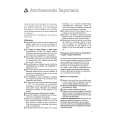
2.5 CHECKUP AND ADJUSTMENT OF MECHANISM PHASE
<Rotary encoder> Set the �I� of the rotary part at the tapped hole as shown in the figure.
<Connect gear> (Note 2) Set the connect gear so that its locating hole meets the hole on the main deck assembly.
<Worm wheel> (Note 2) Set the worm wheel so that its locating hole meets the hole on the main deck assembly.
Note 1 <Main cam gear /Brake control plate> After fitting the main cam\ gear and brake control plat together,set them together so that their locating holes meet the hole on the main \ deck assembly.
<Connect gear 2> (Note 2) Set the connect gear 2 so that its locating hole meets the hole on the main deck assembly.
<Sub cam gear> Set the sub cam gear so that its locating hole meets the hole on the main deck assembly. This state represents that the mechanism is in the EJECT mode, which is the �mechanism assembly mode�.
Note 1: Since the connect gear 2 is tightly fixed to the main deck by caulking, adjust its phase with the connect gear and sub cam gear.
Note 2: The part that needs phase adjustment by the hole on the main deck assembly must exactly be set as the specified phase. There is a fear that some part is installed in a wrong phase because assembling of the mechanism is automated. If so, set every part in the correct phase whenever the mechanism is reassembled.
Fig. 2-5-1
2-15
|
|
|
> |
|