|
|
|
Who's Online
There currently are 6043 guests online. |
|
Categories
|
|
Information
|
|
Featured Product
|
|
|
 |
|
|
There are currently no product reviews.
 ;
Veramente completo, dettagliato e perfetto nella visione. Perfect, thanks!
 ;
Fully functional usable service manual. Considering the age of the manual and device quality was better than expected
;
Thank you very much, I've been very happy to find this manual on "Owner Manual". It's a perfect copy and it has been really useful for my work!
;
It took about 24-hours after my payment before I was able to get to the download. Apparently, payment processing is not 100% automated. That is no big deal, just be aware of that going in.
After I got to it, it was in good shape, easy to read, etc. Not some cheap FAX copy looking thing.
Also, this site was the cheapest I found. Another Plus!
;
Good price, very legible manual, exactly what I needed -- but had to wait a day to actually get the download of the manual. Would have preferred to download it immediately after payment rather than waiting for someone to "process" my order. I was surprised that I had to wait that long.
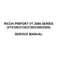
Note: The shape of the monitor assembly varies by the size of the LCD screen. For the 3.5�-type LCD, refer to Fig. 1-4-2. 1.4.3 Disassembly/assembly of monitor assembly (for 3.5�-type LCD) Note: Be careful not to soil or scratch the monitor screen through the disassembly/assembly work. 1. Remove the four screws (1 to 4) in numerical order. While disengaging the six hooks (L4a to L4f) in alphabetical order, remove the monitor cover assembly. Note4f: When removing the monitor cover assembly, be
3. Unplug the wires and FPCs from the two connectors ( c , d ), and then remove the LCD BL board assembly, holder (PWB) and backlight in that order. 4. Remove the LCD module while disengaging it from the four hooks (L4g, L4h, L4j, L4k,). 1.4.4 Disassembly/assembly of hinge assembly (for 3.5�-type LCD) 1. Remove the three screws (5 to 7), and then remove the hinge covers (1) and (2) by disengaging a total of four hooks (L4m, L4n) at the two sides. 2. Separate the SW board assembly and the FPC from the hinge assembly. Note4j: When disassembling/assembling the hinge assembly, pay careful attention to every part not to damage anything. Note4k: When connecting the FPC, arrange the FPC wire by winding it around the shaft (hinge pin) of the hinge assembly by two and a half turns while paying heed to the orientation of the hinge assembly and FPC.
(L 4 c) (L 4 f) (L 4 e)
careful not to damage the FPC and connector.
2. Unlock the connector b and then disconnect the FPC while lifting the hinge assembly upwards to remove it together with the FPC. Note4g: For disconnecting the FPC, unlock the connector first and then lift the hinge assembly upwards. Accordingly, the FPC is disconnected together with the hinge assembly. Note4h: Treat the wires carefully.
� : 0.069N·m (0.7kgf·cm) �� : 0.098N·m (1.0kgf·cm) ��� : 0.147N·m (1.5kgf·cm)
Hinge cover(1) 6� (S 4 d) c MONI. FPC ASSY Note 4 j/ 4 k 5� (S 4 c) (L 4 n) c Note 4 j / 4 k Hinge cover(2) b (L 4 m) 7� (S 4 d)
Monitor cover assy
(L 4 b)
3 (S 4 b)
���
a
4��� (S 4 b) c (L 4 a)
(L 4 d) 1�� (S 4 a)
2�� 4 (S a)
LCD BL PWB d Note 4 f a NoteHinge 4 k 4 j/ assy Note 4 g b
Holder (PWB)
FPC
Back light LCD module
Hinge
Note 4 h 3.5� 4 (L 4 j) (L 4 h) Monitor case assy
(L
k) (L 4 g) b
Bracket(Earth)
a
Fig. 1-4-2 1-8
|
|
|
> |
|