|
|
|
Who's Online
There currently are 5815 guests online. |
|
Categories
|
|
Information
|
|
Featured Product
|
|
|
 |
|
|
There are currently no product reviews.
 ;
I was having a hard time finding the problem with this Mackie 1604 unit. I didn't have a schematic. Went looking on the web and found your site and the price was more then reasonable. Ordered it and within the hour had the manual and within 15 minutes had the unit fixed. Best $4.99 I ever spent. Thank you.
Doug
;
This is a service manual in every sense of the word ( French and German versions of the text are included, as well as English..)
There are explanations of the mechanical and electrical functions, plenty of mechanical drawings, and the needed schematics. The quality of the scanning is excellent - all the component values are clearly legible - and very usefully there are pcb component layouts, so you can find a component on the schematic, and then very quicky pinpoint its physical location on the relevant pcb.
I cannot see how I can give this manual any less than the maximum 5 stars! Great value for money, which will pay for itself immediately. Excellent all round!
;
the manual is great and especially hard to find... thanks for the great service and having a hard to find manuel_
;
Please tell us what you think and share your opinions with others. Be sure to focus your comments on the product. You will receive $2.50 of store credit for Your review.
;
hat alles sehr gut geklappt. Das Servicemaual ist gut zu verwenden. Die Pläne und Schrift
ist klar und leserlich. Außerdem preiswert. Grüße an alle Hifi-Bastler
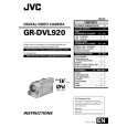
Note: The shape of the monitor assembly varies by the size of the LCD screen. For the 3.5�-type LCD, refer to Fig. 1-4-2. 1.4.3 Disassembly/assembly of monitor assembly (for 3.5�-type LCD) Note: Be careful not to soil or scratch the monitor screen through the disassembly/assembly work. 1. Remove the four screws (1 to 4) in numerical order. While disengaging the six hooks (L4a to L4f) in alphabetical order, remove the monitor cover assembly. Note4f: When removing the monitor cover assembly, be
3. Unplug the wires and FPCs from the two connectors ( c , d ), and then remove the LCD BL board assembly, holder (PWB) and backlight in that order. 4. Remove the LCD module while disengaging it from the four hooks (L4g, L4h, L4j, L4k,). 1.4.4 Disassembly/assembly of hinge assembly (for 3.5�-type LCD) 1. Remove the three screws (5 to 7), and then remove the hinge covers (1) and (2) by disengaging a total of four hooks (L4m, L4n) at the two sides. 2. Separate the SW board assembly and the FPC from the hinge assembly. Note4j: When disassembling/assembling the hinge assembly, pay careful attention to every part not to damage anything. Note4k: When connecting the FPC, arrange the FPC wire by winding it around the shaft (hinge pin) of the hinge assembly by two and a half turns while paying heed to the orientation of the hinge assembly and FPC.
(L 4 c) (L 4 f) (L 4 e)
careful not to damage the FPC and connector.
2. Unlock the connector b and then disconnect the FPC while lifting the hinge assembly upwards to remove it together with the FPC. Note4g: For disconnecting the FPC, unlock the connector first and then lift the hinge assembly upwards. Accordingly, the FPC is disconnected together with the hinge assembly. Note4h: Treat the wires carefully.
� : 0.069N·m (0.7kgf·cm) �� : 0.098N·m (1.0kgf·cm) ��� : 0.147N·m (1.5kgf·cm)
Hinge cover(1) 6� (S 4 d) c MONI. FPC ASSY Note 4 j/ 4 k 5� (S 4 c) (L 4 n) c Note 4 j / 4 k Hinge cover(2) b (L 4 m) 7� (S 4 d)
Monitor cover assy
(L 4 b)
3 (S 4 b)
���
a
4��� (S 4 b) c (L 4 a)
(L 4 d) 1�� (S 4 a)
2�� 4 (S a)
LCD BL PWB d Note 4 f a NoteHinge 4 k 4 j/ assy Note 4 g b
Holder (PWB)
FPC
Back light LCD module
Hinge
Note 4 h 3.5� 4 (L 4 j) (L 4 h) Monitor case assy
(L
k) (L 4 g) b
Bracket(Earth)
a
Fig. 1-4-2 1-8
|
|
|
> |
|