|
|
|
Who's Online
There currently are 5852 guests online. |
|
Categories
|
|
Information
|
|
Featured Product
|
|
|
 |
|
|
There are currently no product reviews.
 ;
El producto satisface las necesidades del servicio t
;
This is a good quality scan of the Operation & Maintenance (Service) Manual for the PAL version of this high-band broadcast umatic, BVU-800P
All schematics and lineup procedures appear to be included in this one manual AFAICT.
The file size is just over 113 MB which gives an idea of the quality and number of pages.
All of the schematics, which contain some fairly small print, are easily readable when you zoom into the page.
John Thompson, Newcastle Upon Tyne, England.
;
Good quality, all schematics of few of models. There is also short form of user manual and regulation manual.
;
Perfect copy of the service manual. you can enlarge every page, and it comes up
with all details.
;
It´s very very nice manual with all, what i need. Original in good quality. Very fast business. Very much thanks...
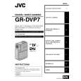
3. 4 REEL DISK ASSY(SUP) 5 REEL DISK ASSY(TU) 6 REEL COVER ASSY NOTE4:
(W 4 ) NOTE 4 4 8 (S 6 a) (W 6 )
WHITE BLACK
(W 5 ) NOTE 5 5 10 (S 6 b) 9 (S 6 a)
Be careful not to attach the REEL DISK wrongly. The Supply side can be identified by the white color at the center.
NOTE 4 , 5
NOTE5: Be careful not to attach the REEL DISK wrongly. The Take-up side can be iden-
REEL DISK ASSY
(W 6 )
tified by the black color at the center.
NOTE6: Perform the following steps for mounting. 1. Align the 2 holes with the pins. 2. Attach the PINCH ROLLER ARM ASSY by aligning the positions. 3. Attach the SUB DECK NOTE 6 ASSY by aligning the 3 5 2,6 positions. 4. Check that the parts below them are located in the correct positions. 4
SUP TU
6 NOTE 6
5. Tighten the 2 screws. 6. Tighten the screw. 7. Attach the 2 SLIT WASHER parts.
4. 7 TENSION ARM ASSY 8 SLANT POLE ARM ASSY 9 TU ARM ASSY 0 SWING ARM ASSY NOTE7: When detaching, remove the spring of the @ PAD ARM ASSY in advance. Pay attention to the attachment po-
1, 7
Fig. 2-4-5
NOTE 7
8 NOTE 7
SPRING
NOTE 8
(P 8 ) NOTE 8 NOTE 10 10
7
11 (S 10 )
NOTE 9 9
sition.
NOTE8:
A
When mounting the SLANT POLE ARM ASSY, hook the spring onto the lug as in diagram A, and fit the combination onto the SLIDE DECK ASSY. After fitting, hook the spring onto the lug of the SLIDE DECK ASSY as in diagram B. Be careful not to lose the spring.
SPRING
B
NOTE 7
NOTE 9
NOTE9: Pay attention to the mounting position.
NOTE0: When detaching, remove the screw
NOTE 10
Fig. 2-4-6
then remove the SWING ARM ASSY by pulling it up and turning it.
2-8
 $4.99 GR-DVP7U JVC
Owner's Manual Complete owner's manual in digital format. The manual will be available for download as PDF file aft…
|
|
|
> |
|