|
|
|
Who's Online
There currently are 6007 guests online. |
|
Categories
|
|
Information
|
|
Featured Product
|
|
|
 |
|
|
There are currently no product reviews.
 ;
very good quality readable manual,printed off very well.
;
The manual was very accurate for the part that I was changing, I was able to order the correct part and had no issues with the replacement procedure. However, I was expecting to have more detailed repairs for the lower drive unit.
 ;
I needed the manual immediately and I got it immediately. I couldn't find this manual anywhere else on the net. The site was easy to traverse, and the price was very reasonable. I'll definitely be back for any future needs.
;
I received a good service manual, with good resolution. Improve the instructions for the purchase because they are not well understood.
For the rest, so good.
Thanks Angel.
;
Very good documentation for the Grundig 2077 model (as well as similar 800/900/1000 series radios). The first two pages are a summary of reception specifications and output capability. The third page is the tuner dial indicator and dial cord routing diagram. the final ~5 pages are the schematics for the various models (including 2077). The scan quality of the schematics are good, adn can be easily read if zoomed in. The documents are in German, not English as stated. It would have been nice to have the tuning sequence and settings, and some trouble shooting materials... or component and wiring map.
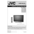
<INNER PWB SIDE> 3.1.18 AV TERMINAL BOARD � Take out the BODY COVER. (1) Remove 5 screws [ A ]. (2) Remove 1 screw [ B ]. (3) Pull out the POWER CORD CLAMP. (4) Remove the nut [ C ] attaching the ANTENNA TERMINAL. (5) Take out the AV TERMINAL BOARD. 3.1.19 SUB DRIVE PWB � Take out the BODY COVER. � Take out the BODY BRACKET. � Take out the MAIN UNIT. (1) Remove 4 screws [ D ]. (2) Take out the PWB HOLDER. (3) Disconnect the connector [CN401] and [CN402]. (4) Remove 6 screws [ E ]. (5) Take out the SUB DRIVE PWB. 3.1.20 POWER PWB � Take out the BODY COVER. � Take out the BODY BRACKET. � Take out the MAIN UNIT. (1) Remove 1 screw [ F ]. (2) Take out the POWER PWB BRACKET. (3) Disconnect the connector [CN90BL], [CN90SE], [CN90AA], [CN90B], [CN90DD] and [CN90G]. (4) Remove 5 screws [ G ]. (5) Take out the POWER PWB. 3.1.21 DIGITAL SIGNAL PWB � Take out the BODY COVER. � Take out the BODY BRACKET. � Take out the MAIN UNIT. � Take out the AV TERMINAL BOARD. � Take out the PWB HOLDER (1) Disconnect the connector [CN001], [CN002], [CN003], [CN0FC] and [CN0LV2]. (2) Remove 1 screw [ H ] attaching the earth wire. (3) Remove 1 screw [ I ]. (4) Remove the both side SHIELD COVER. (5) Take out the DIGITAL SIGNAL PWB. CAUTION: Make sure to perform the "SYSTEM SETTING" on page 1-10, when DIGITAL SIGNAL PWB is replaced.
3.1.22 RECEIVER PWB � Take out the BODY COVER. � Take out the BODY BRACKET. � Take out the MAIN UNIT. � Take out the AV TERMINAL BOARD. � Take out the PWB HOLDER (1) Remove 1 screw [ J ]. (2) Take out the ANALOG PWB BRACKET with PWB. (RECEIVER PWB / ANALOG SIGNAL PWB / REGULATOR PWB) (3) Disconnect the connector [CN10FC], [CN10PH], [CN100R], [CN10PH], [CN100A], [CN100T], [CN100F], [CN10FJ], [CN10FL], [CN10SW], [CN10AA] and [CN10SP]. (4) Remove 4 screws [ K ]. (5) Take out the RECEIVER PWB. 3.1.23 ANALOG SIGNAL PWB � Take out the BODY COVER. � Take out the BODY BRACKET. � Take out the MAIN UNIT. � Take out the AV TERMINAL BOARD. � Take out the PWB HOLDER � Take out the RECEIVER PWB. (1) Disconnect the connector [CN001], [CN002], [CN00D], [CN0J1], [CN0J2], [CN00T], [CN00F] and [CN00G]. (2) Remove 2 screws [ L ]. (3) Take out the ANALOG SIGNAL PWB. 3.1.24 REGULATOR PWB � Take out the BODY COVER. � Take out the BODY BRACKET. � Take out the MAIN UNIT. � Take out the AV TERMINAL BOARD. � Take out the PWB HOLDER � Take out the RECEIVER PWB. (1) Disconnect the connector [CN20D], [CN203] and [CN20B]. (2) Remove 4 screws [ M ]. (3) Take out the REGULATOR PWB. 3.1.25 REAR JACK PWB � Take out the BODY COVER. � Take out the BODY BRACKET. � Take out the MAIN UNIT. � Take out the AV TERMINAL BOARD. (1) Disconnect the connector [CNPH], [CNJ0J2]. (2) Remove 2 screws [ N ]. (3) Take out the REAR JACK PWB.
[CNJ0J1]
and
(No.YA092B)1-15
|
|
|
> |
|