|
|
|
Who's Online
There currently are 5694 guests online. |
|
Categories
|
|
Information
|
|
Featured Product
|
|
|
 |
|
|
There are currently no product reviews.
 ;
Manuals were delivered promptly and were correct as advertised. No issues with the download link which was provided promptly after everything was processed. Very pleasant experience
;
Paid for service manual & got the download fast - worth a visit if you need a service manual
;
It's the manual, I am searching for. Now I am able to repair my Braun A501.
 ;
Great service manual. Unfortunately on page no. 41 there are some details which i can't read.
;
Wonderful service... doubt that I could have made the repairs to my turntable without this service manual. Great help!
Well worth the price paid!
HR-J692US HR-J692UC
SECTION 2 DISASSEMBLY
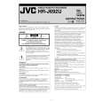
2.1 Manually removing the cassette tape If you cannot remove the cassette tape which is loaded because of any electrical or mechanical failures, manually remove it by taking the following steps. (1) Unplug the power cord plug from the power outlet. (2) Refer to the disassembly procedure of the VCR and perform the disassembly of the major parts before removing the mechanism assembly. (See Fig. 2-1a) (3) Unload the pole base assembly by manually turning the gear of the loading motor until the pole base assembly is hidden behind the cassette lid. In doing so, hold the tape by the hand to keep the slack away from any grease. (See Fig.2-1b ) In case of mechanical failures, while keeping the tension arm assembly free from tension, pull out the tape on the pole base assembly. Take the spring(a) of the pinch roller arm assembly off the hook, and detach it from the tape. (4) Remove the screw (a) of the side frame (L/R). (5) Hold the slack tape and cassette cover together, lift the cassette tape, top frame, cassette holder and side frames (L, R) together from the rear and remove them by dis-engaging the hooks (a) and (b).
Screw(a) Cassette tape Cassette holder Top frame Side frame(R) Screw(a)
Fig.2-1a
Tension arm assembly Pole base assembly Pinch roller arm assembly
Hook(a) Side frame(L) Hook(b)
Fig.2-1c (6) Take up the slack of the tape into the cassette. This completes removal of the cassette tape.
Spring(a)
Direction of unloading
Fig.2-1b
(No.82952)1-5
|
|
|
> |
|