|
|
|
Who's Online
There currently are 5529 guests online. |
|
Categories
|
|
Information
|
|
Featured Product
|
|
|
 |
|
|
There are currently no product reviews.
 ;
really a very good manual even sometimes the quality is no so good as before still very readible and very very useful!
 ;
FAST very good and clear a great unexpensive job!!! very recomended for all people who are preofessional or hobbists as me!!!!!!
;
Thank you very much for this Service Manual, it helped us a lot to repair the M-4318!
...BUT: The parts list is missing and the free parts katalog on web isn't complete, so now we don't know the part numbers of the defect parts :(
We had to build them out of a working machine, and need the numbers to reorder the missing parts now.
;
Very good manual with clear electrical diagrams. Thanks owner-manuals.
;
Great manual, thank you, sony kp46s3 service manual perfectly, i am very happy.
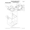
Loading motor board assembly Loading motor Lugs Motor guide
6.5 ± 0.2 mm
LABEL
2. How to install (Centering the mounting position) When the capstan motor has once been removed and then reinstalled out of the initial correct position in the rotational direction, the capstan motor current may be unstable during operation in high or low temperatures. This may result in greater Wow & Flutter and occasionally in power breakdown because of current over - load. Install the capstan motor while following the procedure given below. (The capstan motor is centrally located when the unit is shipped from the factory.) (1) Provisionally tighten the three screws (A) securing the capstan motor. (2) Install the mechanism assembly to which the capstan motor is provisionally fastened on the bottom chassis which incorporates the Main board assembly. (No need to tighten the screws for mounting the mechanism.) Make sure that all the connectors for the mechanism assembly and the Main board assembly are correctly installed as indicated in Fig. 2-2-8b. (3) Making sure that the connector for the capstan motor is correctly mounted, and securely tighten the three screws (A). Note: � When the capstan motor has been replaced with a new one, perform recording in the EP(or LP) mode for at least 2 minutes at normal temperatures immediately be-
Motor pulley Worm gear Belt
Fig. 2-2-7a 2.2.8 Capstan motor 1. How to remove (1) Remove the belt (capstan) on the mechanism assembly back side. (2) Remove the three screws (A) and remove the capstan motor.
Screws(A) Screw(A)
fore starting the FF/REW or SEARCH operations (Aging).
Capstan motor
2.2.9 Pole base assembly (supply or take-up side) 1. How to remove (1) Remove the UV catcher 2 on the removal side by loosening the screw (A). (2) Remove the pole base assembly on the supply side from the mechanism assembly by loosening the screw (B) on the mechanism assembly back side and sliding the pole base assembly toward the UV catcher 2. (3) As for the pole base assembly on the take-up side, turn the pulley of the loading motor to lower the cassette holder because the screw (B) is hidden under the control plate. (See the �Procedures for Lowering the Cassette holder assembly� of 1.3 DISASSEMBLY/ASSEMBLY METHOD.) Further turn the motor pulley to move the cassette holder until the screw (B) is no longer under the control plate (in the half-loading position). Then remove it as done for the supply side by removing the screw (B). Note: � After reinstalling the Pole base assembly and the UV catcher2, be sure to perform compatibility adjustment.
Screw(A) UV catcher2 Screw(A)
Belt
Fig. 2-2-8a
Spacer
Spacer
UV catcher2
Connector for the capstan motor
Fig. 2-2-8b
Screw(B)
Fig. 2-2-9a 2-9
|
|
|
> |
|