|
|
|
Who's Online
There currently are 5886 guests online. |
|
Categories
|
|
Information
|
|
Featured Product
|
|
|
 |
|
|
There are currently no product reviews.
 ;
Excellent printing quality.
A complete and very usefull service manual with all details.
GREAT SERVICE AT VERY LOW PRICE!
A+++++++++++++++++++++++++
;
Excellent printing quality.
A complete and very usefull service manual with all details.
GREAT SERVICE AT VERY LOW PRICE!
A+++++++++++++++++++++++++
;
Excellent printing quality.
A complete and very usefull service manual with all details.
GREAT SERVICE AT VERY LOW PRICE!
A+++++++++++++++++++++++++
;
Excellent printing quality.
A complete and very usefull service manual with all details.
GREAT SERVICE AT VERY LOW PRICE!
A+++++++++++++++++++++++++
;
Excellent printing quality.
A complete and very usefull service manual with all details.
GREAT SERVICE AT VERY LOW PRICE!
A+++++++++++++++++++++++++
1.4 SERVICE POSITION In order to facilitate diagnosis and the repair of the Mechanism assembly, this unit is constructed so as to allow the Mechanism and Main board assemblies to be removed together from the Bottom chassis assembly. 1.4.1 How to take out the Mechanism and Main board assemblies (1) Remove the Top cover, Bracket, Front panel assembly and S JACK board assembly. (Do not remove the flat wire (WR3b) from CN7108 on the S JACK board assembly.) (See 1.3 DISASSEMBLY/ASSEMBLY METHOD.) (2) Lower the cassette holder, and make the preparations required in order to remove the screws from the Mechanism assembly. (Refer to the �Procedures for Lowering the Cassette holder assembly� on pages 1-3 of 1.3 DISASSEMBLY/ASSEMBLY METHOD.) (3) Remove the Roller arm assembly and Drum shield. (See Fig. D4 of 1.3 DISASSEMBLY/ASSEMBLY METHOD.) (4) Take out 2 screws A , 1 screw B , 1 screw C and 1 screw D as shown in Fig. 1-4-1.
JACK board assembly CN7108
C
Fig. 1-4-2 (6) Connect the power cord to the wall socket, and lift the cassette holder. (Before turning on the power make sure that there is nothing which may produce a short circuit, such as faulty soldering.) (7) When performing a diagnosis or repair of the Main board assembly with a cassette tape in place, turn on the power, insert a cassette tape, and turn over the Main board and Mechanism assemblies together. NOTES: � When carrying out diagnosis and repair of the Main board assembly in the service position, be sure to ground both the Main board and
D
Fig. 1-4-1 (5) Remove the Main board and Mechanism assemblies together while holding the edge of the Main board assembly. At this stage be careful of the power cord and prongs of the jacks on the back side. (See Fig. 1-4-2.)
Mechanism assemblies. If they are improperly grounded, there may be noise on the playback picture or the FDP counter display may move even when the mechanism is kept in an inoperative status.
� When performing diagnostics of the tape playback or recording condition in the �SERVICE POSITION�, enter the desired mode before turning the set upside down, and do not change the mode during diagnostics while the set is placed upside down. If you want to switch the mode, turn the set to the normal position.
1-4
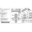 $4.99 HR-S4800U JVC
Quick Start Quick start guide ( sometimes called quick guide ) contains most important information on how to use…
|
|
|
> |
|