|
|
|
Who's Online
There currently are 5987 guests online. |
|
Categories
|
|
Information
|
|
Featured Product
|
|
|
 |
|
|
There are currently no product reviews.
 ;
El producto satisface las necesidades del servicio t
;
This is a good quality scan of the Operation & Maintenance (Service) Manual for the PAL version of this high-band broadcast umatic, BVU-800P
All schematics and lineup procedures appear to be included in this one manual AFAICT.
The file size is just over 113 MB which gives an idea of the quality and number of pages.
All of the schematics, which contain some fairly small print, are easily readable when you zoom into the page.
John Thompson, Newcastle Upon Tyne, England.
;
Good quality, all schematics of few of models. There is also short form of user manual and regulation manual.
;
Perfect copy of the service manual. you can enlarge every page, and it comes up
with all details.
;
It´s very very nice manual with all, what i need. Original in good quality. Very fast business. Very much thanks...
Loading motor board assembly Loading motor Lugs Motor guide
6.5 ± 0.2 mm
LABEL
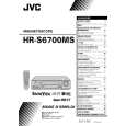
2. How to install (Centering the mounting position) When the capstan motor has once been removed and then reinstalled out of the initial correct position in the rotational direction, the capstan motor current may be unstable during operation in high or low temperatures. This may result in greater Wow & Flutter and occasionally in power breakdown because of current over - load. Install the capstan motor while following the procedure given below. (The capstan motor is centrally located when the unit is shipped from the factory.) (1) Provisionally tighten the three screws (A) securing the capstan motor. (2) Install the mechanism assembly to which the capstan motor is provisionally fastened on the bottom chassis which incorporates the Main board assembly. (No need to tighten the screws for mounting the mechanism.) Make sure that all the connectors for the mechanism assembly and the Main board assembly are correctly installed as indicated in Fig. 2-2-8b. (3) Making sure that the connector for the capstan motor is correctly mounted, and securely tighten the three screws (A). Note: � When the capstan motor has been replaced with a new one, perform recording in the EP(or LP) mode for at least 2 minutes at normal temperatures immediately be-
Motor pulley Worm gear Belt
Fig. 2-2-7a 2.2.8 Capstan Motor 1. How to remove (1) Remove the belt (capstan) on the mechanism assembly back side. (2) Remove the three screws (A) and remove the capstan motor.
Screws(A) Screw(A)
fore starting the FF/REW or SEARCH operations (Aging).
Capstan motor
2.2.9 Pole Base Assembly (supply or take-up side) 1. How to remove (1) Remove the UV catcher 2 on the removal side by loosening the screw (A). (2) Remove the pole base assembly on the supply side from the mechanism assembly by loosening the screw (B) on the mechanism assembly back side and sliding the pole base assembly toward the UV catcher 2. (3) As for the pole base assembly on the take-up side, turn the pulley of the loading motor to lower the cassette holder because the screw (B) is hidden under the control plate. (See the �Procedures for Lowering the Cassette holder assembly� of 1.3 DISASSEMBLY/ASSEMBLY METHOD.) Further turn the motor pulley to move the cassette holder until the screw (B) is no longer under the control plate (in the half-loading position). Then remove it as done for the supply side by removing the screw (B). Note: � After reinstalling the Pole base assembly and the UV catcher2, be sure to perform compatibility adjustment.
Screw(A) UV catcher2 Screw(A)
Belt
Fig. 2-2-8a
Spacer
Spacer
UV catcher2
Connector for the capstan motor
Fig. 2-2-8b
Screw(B)
Fig. 2-2-9a 2-9
|
|
|
> |
|