|
|
|
Who's Online
There currently are 5945 guests online. |
|
Categories
|
|
Information
|
|
Featured Product
|
|
|
 |
|
|
There are currently no product reviews.
 ;
The AKAI 1720 model reel to reel tape recorder described in this Manual is quite an old unit - circa late 1960's. As a consequence, the description of the mechanical details - and adjustments thereof - is quite critical. The manual does this quite well. The schematics are also well presented and have detailed PCB overlays. Probably the only negative is that some half-tone detail has been lost from the original manual as it has been scanned in simple B&W.
 ;
Perfect source for service manuals: fast and professional transaction; high quality, perfect readable and largely scaleable PDF; complete schemes, diagrams and spare part list. Tnx a lot, cu again!!!!
;
I got your link from a friend and I must say that I am really satisfied with your service. Specially this B&O manual I didn't find anywhere on the web... but you could deliver it :-) . You deliver very fast and the copy is of good quality. So your webpage is bookmarked. Thanks
;
This was the Sony CCU-500A Service manual I was looking for.
The price was reasonable.
The permission to download was quck.
I will use Owner-Manual.com for all my manual needs.
;
Excellent printing quality.
A complete and very usefull service manual with all details.
GREAT SERVICE AT VERY LOW PRICE!
A+++++++++++++++++++++++++
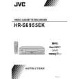
5.2
FINAL ASSEMBLY <M2>
BEWARE OF BOGUS PARTS Parts that do not meet specifications may cause trouble in regard to safety and performance. We recommend that genuine JVC parts be used. 516
1
505
NOTE) INERTIA PLATE should be attached so as to ser small diameter of central round hole above.
515
g
520
522 521
503
502
d
519A 515 519
e
a
d
MECHANISM ASSY<M4> 516
g
533
c
510
510
NOTE) When attaching ROLLER ARM ASS'Y, attach the hook(L3c) before the spring(P3a). NOTE) After attached ROLLER ARM ASS'Y, tighten screw(S3g) with slit washer(W3a).
503 MAIN BOARD ASSY<03>
532
Q 30 03
510
517
g
Insert the bushing of POWER CORD so as not to twist the cord.
533
b c'
D 30 01
dc e
JS3001
REAR SIDE
504
533
CN5 00 1
1 00 JS 3
00 Q3
2
a
d'
c' b
b h
<Phase alignment> Accord the position of V gap on R. Encoder and PWB silk " ". Accord the position of Boss on R. Encoder and PWB silk " ".
511
k h a f g d' c' b f b c'
523
e
For the prevention of the DRUM FPC damage. When you attach the MECHA UNIT on B. CHASSIS. Attach the MECHA UNIT after the positioning boss "z" of the B. CHASSIS is matched to the positioning hole of the MECHA UNIT.
"Z"
To main CN7001
b
501
501A
f
BACK SIDE
WR4
ADV. JOG BOARD ASSY<38>
Front panel back side
f
501B
CN7003
f
f
530
ONLY USED FOR HR-S6955EK
534
512
f
f
529 [HR-S6955EK]
From CAPSTAN MDA Right side
Right side
NOTE
1. Insert direction of FCC WIRE as follows. Right side Back side
electrode side
1
supporting side
CN5001 CN2001
2. FFC WIRE and DRUM FPC WIRE should be insert as follows. OK NG 90
DRUM
CN501
CN
CN
CN
A/C HEAD
3. Insert direction of POWER CORD.
U/U(C)/JPN WHITE LINE
CN7102
Except U/U(C)/JPN BLUE
CN7105
NEUTRAL
NEUTRAL
CN5001
CN5001
CN7001
ONLY USED FOR HR-S6955EK
from FRONT PANEL Right side For JOG
5-2
|
|
|
> |
|