|
|
|
Who's Online
There currently are 5816 guests online. |
|
Categories
|
|
Information
|
|
Featured Product
|
|
|
 |
|
|
There are currently no product reviews.
 ;
Das ging ja sehr unkompliziert hat bestens geklappt und die Quallität ist auch noch gut.
Vielen Dank dafür.
;
Everything okay, thanks a lot. It was a pleasure for me to make a deal with you.
;
A deal without problems, very fast and the manual is a good quality. Sorry for the my english.
;
Superb service and excellent quality of the document received
;
no problems with the purchase of a circuit diagram
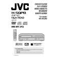
DISASSEMBLY INSTRUCTIONS
1. REMOVAL OF MECHANICAL PARTS AND P.C. BOARDS
1-1: TOP CABINET AND FRONT CABINET (Refer to Fig. 1-1) 1. 2. 3. 4. 5. 6. 7. Remove the 5 screws 1. Remove the Top Cabinet in the direction of arrow (A). Disconnect the following connector: (CP651). Unlock the 8 supports 2. Remove the Front Cabinet in the direction of arrow (B). Remove the 2 screws 3. Remove the Operation PCB in the direction of arrow (C).
Top Cabinet
1-3: DVD DECK (Refer to Fig. 1-3) 1. Make the short circuit on the position as shown Fig. 1-3 using a soldering. If you remove the DVD Deck with no soldering, the Laser may be damaged. 2. Unlock the support 1 and remove the Deck Top Holder in the direction of arrow (A). 3. Remove the 2 screws 2. 4. Remove the screw 3. 5. Remove the screw 4. 6. Disconnect the following connectors: (CP2601, CP2602, CP2603). 7. Remove the DVD Deck in the direction of arrow (B). 8. Remove the 3 screws 5. 9. Remove the Front Angle in the direction of arrow (C). 10. Remove the screw 6. 11. Remove the DVD Angle.
DVD Deck Deck Top Holder
1 1
1 1
4 3
Pick Up PCB
2
(A)
1
Front Cabinet
1 2
(B)
2 2
2
3 2 2
(A)
3
CP651 Operation PCB
(B)
Make the sort circuit using a soldering. DVD Angle
2 2
(C)
2
5
Fig. 1-1 1-2: FLAP (Refer to Fig. 1-2) 1. Open Flap to 90� and flex in direction of arrow (A), at the same time slide in direction of arrow (B). 2. Then lift in direction of arrow (C). NOTE
5
5
(C) CP2601 CP2603 CP2602
6
Front Angle
Fig. 1-3
(A)
When the installation of the DVD Deck, remove all the soldering on the short circuit position after the connection of Pick Up PCB and DVD PCB connector.
(C)
(B)
Flap
Fig. 1-2
1-1
|
|
|
> |
|