|
|
|
Who's Online
There currently are 6042 guests and
1 member online. |
|
Categories
|
|
Information
|
|
Featured Product
|
|
|
 |
|
|
There are currently no product reviews.
 ;
The service manual was a copy of the original from Wirlpool. The quality was good, all neccecary information was available including the service-codenumbers, so I could order the right part to be replaced for repair.
Downloding was no probem after the payment.
Thanks for the service!
;
Good,readable manual. I found other manuals that were not readable when it came to part ID, but the one downloaded from owner-manual.com was better than expected. I will do buisness with owner-manual.com again.
;
Service Manual that I received was very helpful to me. Thank you.
;
The manual is well organized and is easy to read. The chapters are following normal way to proceed.
;
This scanned manual is well done in that most all the pages except for one is straight and clear- the way I would do them. One page was upside down but that happens. For the money that is charged on this site you get a pretty good deal. Now with complex repairs, I still prefer to us paper manuals which I have to buy at stereomanuals but the one I got here was much less than the $45 he was charging but this is a larger than normal manual for three different units. I am a picky manual user because I have used original manuals from Sony and Teac.
SECTION 3 DISASSEMBLY
3.1 3.1.1 (1) (2) (3) DISASSEMBLY PROCEDURE REMOVING THE REAR COVER Unplug the power cord. Remove the 16 screws [A] as shown in the Fig. 1. Withdraw the REAR COVER toward you. 3.1.5 CHECKING THE PW BOARD � To check the back side of the PW Board. (1) Pull out the CHASSIS. (Refer to REMOVING THE CHASSIS). (2) Erect the CHASSIS vertically so that you can easily check the back side of the PW Board. 3.1.6 CAUTION � When erecting the CHASSIS, be careful so that there will be no contacting with other PW Board. � Before turning on power, make sure that the wire connector is properly connected. � When conducting a check with power supplied, be sure to confirm that the CRT EARTH WIRE (BRAIDED ASS'Y) is connected to the CRT SOCKET PW board. 3.1.7 WIRE CLAMPING AND CABLE TYING (1) Be sure to clamp the wire. (2) Never remove the cable tie used for tying the wires together. Should it be inadvertently removed, be sue to tie the wires with a new cable tie.
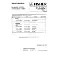
3.1.2 REMOVING THE AV TERMINAL BOARD � Remove the REAR COVER. (1) Remove the 5 screws [B] as shown in the Fig. 1. (2) Withdraw the AV TERMINAL BOARD toward you. 3.1.3 REMOVING THE CHASSIS � Remove the REAR COVER. (1) Slightly raise the both sides of the CHASSIS by hand and remove the 2 claws under the both sides of the CHASSIS from the front cabinet. (2) Withdraw the CHASSIS backward. (If necessary, take off the wire clamp, connectors etc.) 3.1.4 REMOVING THE SPEAKER � Remove the REAR COVER. (1) Remove the 2 screws [C], and remove the SP HOLDER as shown in Fig. 1. NOTE : When removing the screws [C] of the SP HOLDER, remove the lower side screw first, and then remove the upper one. (2) Remove the claw [D] push the SP HOLDER as shown in Fig. 2. (3) Follow the same steps when removing the other SPEAKER.
SP HOLDER
SPEAKER D
SPEAKER
CLAW SP HOLDER SP HOLDER [SIDE VIEW]
Fig.2
1-6 (No.52199)
|
|
|
> |
|