|
|
|
Who's Online
There currently are 6043 guests online. |
|
Categories
|
|
Information
|
|
Featured Product
|
|
|
 |
|
|
There are currently no product reviews.
 ;
It´s very very nice manual with all, what i need. Original in good quality. Very fast business. Very much thanks...
;
Purchased the manual that I was looking for at a great price and could download it easily.. Great service experience and for future purchases I plan to use the site.
Thank you very much
;
Exactly what was needed to assess the product - excellent value and great service
;
A site where discontinualed schematic diagrams and back dated information can be found on discontinued radios tv's and any electronic equipment can be found. Newer manuals either Service and operating manuals. Radio amateurs should find this site a great source for ham radio equipment manuals. I will return to this site should I need information on any electrical equipment. priced easy to download in a PDF format and print pages need to undertake the repair.
;
Quality scan of the original. All the detail necessary to troubleshoot, repair and adjust the unit. I'm sure I will be downloading more manuals in the future as the need arises.
3.2
CD mechanism assembly section
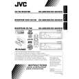
� Remove the CD mechanism assembly from the main body. (See "3.1.5 Removing the CD mechanism assembly".) 3.2.1 Removing the mechanism control board (See Fig.1) (1) From the bottom side of the CD mechanism assembly, solder the short sections on the flexible wire. Caution: Solder the short sections on the flexible wire before disconnecting the flexible wire from the connector CN601 on the mechanism control board. If you do not follow this instruction, the CD pickup may be damaged. (2) Disconnect the flexible wire from the connector CN601 on the mechanism control board. (3) Disconnect the flexible wire from the connector CN602 on the mechanism control board. (4) Remove the solders from the soldered sections a on the mechanism control board and remove the wires of the feed motor. (5) Remove the solders from the soldered sections b on the mechanism control board, and remove each wire of the spindle motor and other parts. (6) Remove the five screws A attaching the mechanism control board. Caution: When reassembling, remove the solders from the short sections after connecting the flexible wire to the connector CN601 on the mechanism control board.
Short sections Flexible wire
CD mechanism assembly
A
Feed motor
a
CN601
A
A
A
Spindle motor
b
A
CN602
Mechanism control board Fig.1
1-12 (No.MA191)
|
|
|
> |
|