|
|
|
Who's Online
There currently are 6043 guests online. |
|
Categories
|
|
Information
|
|
Featured Product
|
|
|
 |
|
|
There are currently no product reviews.
 ;
The manual was exact the thing that was promised. My old car stereo is working again thanks to the information supplied.
;
I PURHASED THIS PRODUCT BECAUSE I WAS HAVING PROBLEMS WITH MY CDR20 HARMAN KARDON RECORDER. WHICH I PURCHASED NEW 12 YEARS AGO. AFTER REVIEWING THE MANUAL, I WAS ABLE TO ADJUST THE TENSIONER IN THE SYSTEM. WORKS LIKE A CHAMP!.
SAVED ME AT LEAST 100.00 WHICH WAS WHAT A SERVICE REPAIR STATION WANTED. GREAT MANUAL EASY TO READ. SPECIALLY AFTER I PRINTED THE PAGES WHICH DEALT WITH MY RECORDER. THANKS A LOT!!!!!!!!
 ;
You can fully trust on this one!
All the schematics are very crear an in one piece per page
;
I have never bought a service manual which is as competely readable as this althogh it was a scanned pdf. Thank you for this succesful manual also cheaper than other sites.
;
Thanks for a very good and readable servicemanual. Just what I needed as a "dinosaur technician". I really recommmend this site and will come back.
Åsbjörn
KD-S680
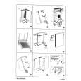
Removing the feed motor assembly (See Fig.10)
Prior to performing the following procedure, remove the CD mechanism control board, the front bracket (loading motor) and the CD mechanism assembly. 1. Remove the two screws F assembly. and the feed motor
Pickup unit FD screw Feed motor assembly Part i
Part j
F
FD gear
Pickup unit
Removing the pickup unit (See Fig.10 and 11)
Prior to performing the following procedure, remove the CD mechanism control board, the front bracket (loading motor), the CD mechanism assembly and the feed motor assembly.
Nut push spring plate
Fig.10
G
Pickup mount nut
1. Detach the FD gear part of the pickup unit upward. Then remove the pickup unit while pulling out the part i of the FD screw. ATTENTION: When reattaching the pickup unit, reattach the part j of the pickup unit, then the part i of the FD screw. 2. Remove the screw G attaching the nut push spring plate and the pickup mount nut from the pickup unit. Pull out the FD screw.
FD screw
Pickup unit
Fig.11
k
k
Removing the spindle motor (See Fig.12 and 13)
Prior to performing the following procedure, remove the CD mechanism control board, the front bracket (loading motor), the CD mechanism assembly and the feed motor assembly. 1. Turn up the CD mechanism assembly and remove the two springs k on both sides of the clamper arms. Open the clamper arm upward. 2. Turn the turn table, and remove the two screws H and the spindle motor. Fig.12
Spindle motor
H
H
Fig.13
1-10
|
|
|
> |
|