|
|
|
Who's Online
There currently are 6043 guests online. |
|
Categories
|
|
Information
|
|
Featured Product
|
|
|
 |
|
|
There are currently no product reviews.
 ;
Impressively thorough. Even the simple operators manual helped me "fix" one of the 2 CD players in the unit. This unit reads CD's from the top so they should be installed in the magazines "upside down" from typical CD players. The CD player service manual helped me unjam a stuck carriage because somebody transported the box laying down loaded with CD's. A little lens cleaning & the player now works well! Thanks for you help at a great price! Joe
;
I was skeptical at first but later found the manual to be good quality for the price. It took a couple hours to receive the email with the download link, well worth the wait. Thanks.
;
very helpful, I could not have cleaned motherboard and replaced the main fan without it
 ;
Good manual, schematics nice and clear with good quality scanning. Woul dhave been nice to have immediate access after purchasing though.
;
I was very glad recieving the service manal from You. Manuals were delivered promptly and were correct as advertised. A complete and very usefull service manual with all details. Thank you!
3.2
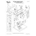
CD mechanism assembly section
� Remove the CD mechanism assembly from the main body. (See "3.1.5 Removing the CD mechanism assembly".) 3.2.1 Removing the mechanism control board (See Fig.1) (1) From the bottom side of the CD mechanism assembly, solder the short sections on the flexible wire. Caution: Solder the short sections on the flexible wire before disconnecting the flexible wire from the connector CN601 on the mechanism control board. If you do not follow this instruction, the CD pickup may be damaged. (2) Disconnect the flexible wire from the connector CN601 on the mechanism control board. (3) Disconnect the flexible wire from the connector CN602 on the mechanism control board. (4) Remove the solders from the soldered sections a on the mechanism control board and remove the wires of the feed motor. (5) Remove the solders from the soldered sections b on the mechanism control board, and remove each wire of the spindle motor and other parts. (6) Remove the five screws A attaching the mechanism control board. Caution: When reassembling, remove the solders from the short sections after connecting the flexible wire to the connector CN601 on the mechanism control board.
Short sections Flexible wire
CD mechanism assembly
A
Feed motor
a
CN601
A
A
A
Spindle motor
b
A
CN602
Mechanism control board Fig.1
(No.MA162)1-11
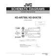
 $4.99 KD-SHX750 JVC
Parts Catalog Parts Catalog only. It's available in PDF format. Useful, if Your equipment is broken and You need t…
|
|
|
> |
|