|
|
|
Who's Online
There currently are 6019 guests online. |
|
Categories
|
|
Information
|
|
Featured Product
|
|
|
 |
|
|
There are currently no product reviews.
 ;
Dear Sirs,
Thank you for the fast support, the manual does provide all necessary information to repair the radio. All schematics are in a good quality for reading.
The manual fits 100% to my requirements as a technican.
Kind regards Thomas
;
the big video recorder format s-vhs many features delicate in loading system of the cassette. Such machines are no longer manufactured, it would be too expensive.
 ;
THIS MANUAL IS VERY GOOD AND VERY CLEAR
PLEASE NOTE IT DOES NOT CONTAIN THE SETUP INFORMATION TO ALIGHN THE GEARS IN THE CD MECH IT DOES SHOW ALL THE PARTS AND THEIR LOCATIONS .
;
Complete service and operation manual. All schematics are there, all circuit boards AND add-on boards. Including exploded views ,component names and specifications. Also electrical and mechanical adjustment procedures are in this manual. This manual also covers the more advanced BR-S811E unit. Scan quality is fair and usable.
;
High quality scan of original Service Manual. Everything´s fine!
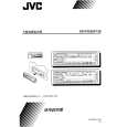
KS-FX230
<< Cassette mechanism section >>
Removing the head relay board (see Fig.1)
1. Desolder the lead wires of the loading motor at the 2 positions shown (Red and Black). 2. Desolder the lead wire of the head at the 3 positions shown (RED, Yellow and Black). 3. Remove the three screws A securing the head relay board. 4. Shift the interlocking section a securing the head relay board in the direction shown by the arrow to remove the board. Black A Red Yellow Head relay board Red Black A A a
Removing the load arm ass'y (see Fig.2)
1. Using tweezers, detach the mylar washer 1 securing the load arm ass'y and pull out the load arm ass'y. NOTE : When reassembling, be sure to use a new mylar washer. 2. Shift the load arm ass'y counter clockwise. 3. Remove the load arm ass'y from the catch.
Fig. 1 Catch
Removing the cassette holder and arm ass'y (see Fig.3)
1. Remove the head relay board. 2. Remove the load arm ass'y. 3. Apply DC 6V to the lead wire of the loading motor ass'y and turn the load gear ass'y to the position shown in Fig. 3. 4. Remove the screw B securing the cassette holder and holder arm ass'y. 5. Shift the cassette holder and holder arm ass'y in the direction shown by the arrow and remove them from the interlocking section b of the sub chassis ass'y. Load arm ass'y Fig. 2 1
Cassette holder
B
Holder b C D Sub chassis ass'y Loading gear ass'y Loading motor ass'y Fig. 3 Apply DC 6V
Removing the sub chassis ass'y (see Fig.4)
1. Remove the head relay board. 2. Remove the load arm ass'y. 3. Remove the cassette holder and holder arm ass'y. 4. Remove the two screw C and D securing the sub chassis ass'y. NOTE : When removing the sub chassis ass'y, the mode gear may become detached. In this case, set it back to the original position.
1-4
 $4.99 KSFX230 JVC
Owner's Manual Complete owner's manual in digital format. The manual will be available for download as PDF file aft…
|
|
|
> |
|