|
There are currently no product reviews.
 ;
One address for rare manuals.Very good copy. Thank you.
Your
Klaus Husse
;
All ok. I pay 5 $ and now i have 92 pages of good scaned service manual for my oooooold akai. Now i will try to repair it.
;
good and ok, very nice , good and ok, very nice, good and ok, very nice
;
Super manual it contains all the things you need to service your Marantz 2100.
;
A very easy to understand and use manual. Well worth the money.
KS-FX483R,KS-FX480R,KS-FX43R
2.1.4 Removing the heat sink (See Fig.4) � Prior to performing the following procedure, remove the front panel assembly. (1) Remove the two screws B and two screws C attaching the heat sink on the left side of the body, and remove the heat sink.
C
B
C
Heat sink Fig.4
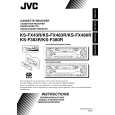
2.1.5 Removing the rear panel (See Fig.5 ) � Prior to performing the following procedure, remove the front panel assembly and bottom cover. (1) Remove the two screws D, two screws E and screw F attaching the rear panel on the back of the body. Reference: During reassembly, before fixing the rear panel onto the main body, insert the ST remote wire into the slot. (For KS-FX43R only)
Insert ST remote cable into the slot (KS-FX43R only)
D
F
D
E
Fig.5 2.1.6 Removing the main board (See Fig.6) � Prior to performing the following procedure, remove the front panel assembly, bottom cover, front chassis, heat sink and rear panel. (1) Remove the two screws G attaching the main board on the top chassis. (2) Disconnect the two connectors CN901 and CN902 on the main board from the cassette mechanism assembly.
Main board
G
CN902
G
CN901 ST remote cable (KS-FS43R only)
Fig.6
1-4 (No.49812)
|