|
|
|
Who's Online
There currently are 5960 guests online. |
|
Categories
|
|
Information
|
|
Featured Product
|
|
|
 |
|
|
There are currently no product reviews.
 ;
Excellent printing quality.
A complete and very usefull service manual with all details.
GREAT SERVICE AT VERY LOW PRICE!
A+++++++++++++++++++++++++
;
Very fast and perfect delivery. Clear and well scanned. A lot of work professionally realized.
Again thak you a lot
 ;
This manual is accurate and of high quality. It is only volume 2 of the service manual. This is schematic, parts lists, and exploded mechanical drawings. The theory of operation and the diss-assembly instructions are in volume 1. The unit can be tricky to dis-assemble portions of so the volume 1 manual can be important. The product description of the manual is accurate but it does not say anything about volume 1 and the image of the front page does clearly say Volume 2.
;
Wellll again thank you very much fast and effective. Clear and well done for such an old TV!!!!
;
It has all the information you will need to fix it. The main circuit diagram is only A4 but being a PDF, you can print it to any size - I did it on two sheets of A3 and it didnt lose any detail - just made it readable when pinned up above the bench. I've found the fault, just need to buy some obscure bits to get it going again!
I cant fault the process, I paid for the manual in the morning and it was ready to download by lunch time.
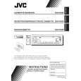
2.2.13 Removing the gear base arm / gear base link assembly (See Fig.23 to 25) (1) Move the gear base arm in the direction of the arrow. (2) Insert a slotted screwdriver to the gear base spring under the gear base arm, and release the gear base arm upward from the boss on the gear base assembly. (3) Remove the gear base arm from the main chassis while releasing the two joints s. (4) Move the gear base link assemby in the direction of the arrow to release the two joints t. REFERENCE: When reattaching the gear base arm, make sure that the boss on the gear base assembly is inside the gear base spring. 2.2.14 Removing the FFC pad (See Fig.25 and 27) (1) Push each joint hook u of the FFC pad and remove toward the bottom.
Joint t
Gear base arm Joints s
Hook u FFC pad Hook u
Gear base link assembly
Joint t
Fig.23
Gear base spring
Gear base arm Screwdriver
Fig.24
Gear base link assembly
Gear base arm
FFC pad Fig.25
1-14 (No.49845)
 $4.99 KS-FX490 JVC
Owner's Manual Complete owner's manual in digital format. The manual will be available for download as PDF file aft…
|
|
|
> |
|