|
|
|
Who's Online
There currently are 6043 guests online. |
|
Categories
|
|
Information
|
|
Featured Product
|
|
|
 |
|
|
There are currently no product reviews.
 ;
Superb rendition. Drawings (schematics) complete and unabridged. I do a great deal of vintage audio restoration. Documentation is essential for successful repairs. I have found sources over the years that offer good documentation, but rarely all that is necessary. Owner's Manuals has filled that void with complete and legible documentation. They have narrowed my "favorites" to a more manageable collection. This Denon manual in particular contained the latest revisions level, and offered alterations favorable to updating the item. The Illustrated Parts Breakdown (IPB) was well enough detailed to simplify part symbols and physical locations. You will not be disappointed!
;
Clear and concise. Saved me a lot of time and money.
;
Superb manual. Exactly what I ordered and made available in a very timely manner.
 ;
very fast detailed and accurate hope to do business again
;
This was precisely what I was looking for. Complete and good quality!
KS-FX8
2.1.6 Removing the main board (See Fig.7) � Prior to performing the following procedures, remove the front panel assembly, bottom cover, front chassis assembly, heat sink and rear panel. (1) Remove the two screws H attaching the main board on the top chassis. (2) Disconnect the connector CP701 on the main board from the cassette mechanism assembly.
Main board
H
H
CP701
Fig.7 2.1.7 Removing the cassette mechanism assembly (See Fig.8) � Prior to performing the following procedures, remove the front panel assembly, bottom cover, front chassis assembly, heat sink, rear panel and main board. (1) Disconnect the card wire from the connector CN403 on the mecha board. (2) Remove the four screws J attaching the cassette mechanism assembly from the top chassis, take out the cassette mechanism assembly. (3) From the bottom side of the cassette mechanism assembly, disconnect the wire from the connector on the head board.
Cassette mechanism assembly
J
J
Connector
Head board
Mecha board
J
CN403
Fig.8
J
Top chassis
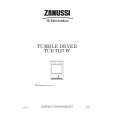
2.1.8 Removing the mecha board (See Fig.9) � Prior to performing the following procedures, remove the front panel assembly, bottom cover, front chassis, heat sink, rear panel, main board and cassette mechanism assembly. (1) Remove the screw K attaching the mecha board. (2) Bend the hook f in the direction of the arrow 1 and move the mecha board in the direction of the arrow 2. (3) Remove the mecha board from the mecha bracket (L) of the top chassis.
Top chassis
Mecha board Hook e
K
2
1
Mecha bracket (L)
Fig.9
(No.49826)1-5
|
|
|
> |
|