|
|
|
Who's Online
There currently are 5891 guests online. |
|
Categories
|
|
Information
|
|
Featured Product
|
|
|
 |
|
|
There are currently no product reviews.
 ;
It's complete and helpful manual with good quality of scan. Thanks very much.
;
The service was quick and simple, finding the service manual easy and it appears to be the original with colour schematics. It contained the info I was after and so sorted the problem.
I have copied it to CD and attached the envelope to the inside back cover of the owners manual. Good manual and excelent service. Robin Wood, Wood Electronics, New Zealand.
;
Exactly what was needed to assess the product - excellent value and great service
 ;
Nice to have the service manual for the Sony DCR-TRV345E now. The document is of excellent quality.
;
MACKIE HR824 26 pages English-only Service Manual contains:
1) HR824 technical overview with the description of front and rear panel switches.
2) HR824 specs
3) Block Diagram
4) Wiring Diagram
5) Packaging management
6) Spare part & final assembly list (for PCB rev A and B) + exploded view
7) Test Procedures (where, how to measure voltage...) including Test Point diagram on the PCB.
8) IC and Transistor charts.
Excellent guide: very clear, good scan quality enabling us to print readable diagram :-)
Note:
Mackie HR824 make extensive use of surface mount devices (SMD). Service on the HR824 must
only be undertaken by experienced service technicians with the right tools, experience and patience to perform surface mount rework when needed.
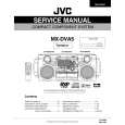
MX-DVA5
Removing the tuner board (See Fig.11 and 13)
Prior to performing the following procedure, remove the metal cover and CD / DVD changer unit. 1. Disconnect the card wire from connector CON01 on the tuner board. 2. Remove the two screws L attaching the tuner board.
CON01
Rear panel
Main board
Tuner board
Fig.13
Removing the rear panel
(See Fig.14)
Prior to performing the following procedure, remove the metal cover, CD / DVD changer unit, heat sink & Amp. board and tuner board. 1. Remove the three screws N and five screws M attaching the rear panel.
Rear panel
M N
Fig.14
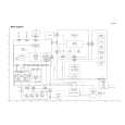
Removing the main Board (See Fig. 15)
Prior to performing the following procedure, remove the metal cover, CD / DVD changer unit, heat sink & Amp. board tuner board and rear panel. 1. Disconnect the card wire from connector FCW3 and the harness from connector JCW1, JCW2, and HCW3 on the main board. 2. Disconnect the harness from connector PCW1 on the power transformer board. 3. Remove the screw G attaching the main board holder. (See Fig.8) 4. Remove the two screws O attaching the heat sink and bottom chassis.
PCW1 Power transformer board FCW3 JCW2 JCW1 HCW3 Main board
O
Fig.15
1-9
 $4.99 MX-DVA5 JVC
Parts Catalog Parts Catalog only. It's available in PDF format. Useful, if Your equipment is broken and You need t…
|
|
|
> |
|