|
|
|
Who's Online
There currently are 5923 guests online. |
|
Categories
|
|
Information
|
|
Featured Product
|
|
|
 |
|
|
There are currently no product reviews.
 ;
a solid deal - quick and without any problems.
I life in europe - with downloads no loosing time
once again
 ;
got exactly what i ordered in a very timely manner. will use again for other manuals
;
I'm happy. Good quality. Very helped me with my work..............................
;
This is the second Manual I have ordered from owner-manuals, I give it five stars because it is exactly what I expected given the age of the equipment. So the contents look a bit aged and the pictures a bit grainy, it fulfills my needs and I am glad I can still get hold of them.
;
thank u so much for this manual that was so cheap that i thought it was a scam but i gambled anyway because it was too good of a deal to pass up and behold,the manual has everything and details of everything even the screws and im still amazed and very happy with my manual .so take my word and jump on it before they realize how cheap they selling thier manuals..thank you so much for taking time to read my thoughts
MX-G68V/MX-G65V
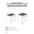
Removing the tuner board (See Fig.11 and 13)
Prior to performing the following procedure, remove the metal cover and CD changer unit. 1. Disconnect the card wire from connector CON01 on the tuner board. 2. Remove the two screws L attaching the tuner board.
Main board CON01
Rear panel
Tuner board
Fig.13
Removing the rear panel
(See Fig.14)
Prior to performing the following procedure, remove the metal cover, CD changer unit, heat sink & amplifier board and tuner board. 1. Remove the one screw M, three screws N and three screws N' attaching the rear panel.
Rear panel
N' M N
Fig.14
Removing the main Board (See Fig. 15)
Prior to performing the following procedure, remove the metal cover, CD changer unit, heat sink & amplifier board, tuner board and rear cover. 1. Disconnect the card wire from connector FCW3 and the harness from connector JCW1, JCW2, ECW1 and HCW3 on the main board. 2. Disconnect the harness from connector PCW1 on the power transformer board. 3. Remove the screw G attaching the main board holder. (See Fig.8) 4. Remove the two screws O attaching the heat sink and bottom chassis.
FCW3 ECW1 JCW1 JCW2 HCW3 Main board
O
Transformer board
PCW1
Fig.15
1-8
|
|
|
> |
|