|
|
|
Who's Online
There currently are 6043 guests online. |
|
Categories
|
|
Information
|
|
Featured Product
|
|
|
 |
|
|
There are currently no product reviews.
 ;
Exactly what was needed to assess the product - excellent value and great service
 ;
Nice to have the service manual for the Sony DCR-TRV345E now. The document is of excellent quality.
;
MACKIE HR824 26 pages English-only Service Manual contains:
1) HR824 technical overview with the description of front and rear panel switches.
2) HR824 specs
3) Block Diagram
4) Wiring Diagram
5) Packaging management
6) Spare part & final assembly list (for PCB rev A and B) + exploded view
7) Test Procedures (where, how to measure voltage...) including Test Point diagram on the PCB.
8) IC and Transistor charts.
Excellent guide: very clear, good scan quality enabling us to print readable diagram :-)
Note:
Mackie HR824 make extensive use of surface mount devices (SMD). Service on the HR824 must
only be undertaken by experienced service technicians with the right tools, experience and patience to perform surface mount rework when needed.
;
This Service manual is very well scanned and its clean to read, no any anti-theft words that un-english could understand. I got my CCD600 working with this manual and it´s clear shematics :)
;
I was very pleased with the service provided and was surprised at how good the quality was of the manual. I thought it may be a third generation copy or so, but it is as good as the websites that charge 3 times this much. I repair some electronics for family and friends without charge, so this is perfect for me. Thank you very much.
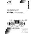
3.1.5 Removing the heat sink & amp. Board (See Fig. 8, 11 and 12) � Prior to performing the following procedure, remove the metal cover and CD changer unit. (1) Disconnect the card wire from the connector ACW1 and the harness from the connector ACW2 on the amp. board. (2) Remove the four screws I attaching the heat sink cover to the rear panel. Remove the heat sink cover. (3) Remove the four screws J attaching the heat sink and two screws K attaching the speaker terminal to the rear panel. (4) After moving the heat sink upward, remove the claws. Then pull out the heat sink & amp. board inward. 3.1.6 Removing the tuner board (See Fig. 12 and 13) � Prior to performing the following procedure, remove the metal cover. (1) Disconnect the card wire from the connector CON01 on the tuner board. (2) Remove the two screws L attaching the tuner board to the rear panel. 3.1.7 Removing the rear panel (See Fig. 12) � Prior to performing the following procedure, remove the metal cover, CD changer unit, heat sink & amp. board and tuner board. (1) Remove the screw M and three screws N attaching the rear panel.
Rear panel
I
Heat sink cover
I
Fig.11
Rear panel
J
Claws Heat sink
L K M
Speaker terminal
J
N
Fig.12
CON01 Main board Rear panel
Tuner board
Fig.13
(No.MB080)1-9
 $4.99 MX-GA8 JVC
Owner's Manual Complete owner's manual in digital format. The manual will be available for download as PDF file aft… 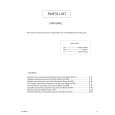 $4.99 MX-GA8 JVC
Parts Catalog Parts Catalog only. It's available in PDF format. Useful, if Your equipment is broken and You need t…
|
|
|
> |
|