|
|
|
Who's Online
There currently are 5872 guests online. |
|
Categories
|
|
Information
|
|
Featured Product
|
|
|
 |
|
|
There are currently no product reviews.
 ;
Complete manual included schematics layouts and alignment procedure, clear to read and magnify, extremely pleased with manual and owner manual . com's service
;
perfect, i am very satisfait for the réception of the sansui r-5l service manual, thank you very much
;
Thank you, this is a rare document. Few others have it, but they charge way more for a download.
Great deal (even if you have to wait a few hours to get it).
;
The purchased manual is an high quality scan of the original Philips paper-based Service Manual. I am very satisfied!
 ;
The purchased manual is an scan of the original Panasonic paper-based Service Manual. Unfortunately the contrast is not perfect, but I am satisfied anyway!
MX-GT700
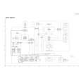
Removing the heat sink & amp. board (See Fig.8, 11 and 12)
Prior to performing the following procedure, remove the metal cover and CD changer unit. 1. Disconnect the card wire from the connector ACW1 and the harness from the connector ACW2, ACW5 and ACW6 on the amp. board. 2. Remove the four screws I attaching the heat sink cover to the rear panel. Remove the heat sink cover. 3. Remove the four screws J attaching the heat sink and two screws K attaching the speaker terminal to the rear panel. 4. After moving the heat sink upward, remove the claws. Then pull out the heat sink & amp. board inward. If the voice board is removed at this time, it will be able to work comfortably.
Heat sink cover
Joint2
(Bottom side)
H
Fig.10
Rear panel
I
I
Removing the fan motor (See Fig.8 and 12)
Prior to performing the following procedure, remove the metal cover and heat sink cover.
1. Disconnect the harness from the connector ACW5 on the amp. board. Fig.11
L J
Rear panel
2. Remove the two screws L attaching the fan motor Claws to the rear panel. Heat sink
M N K
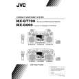
Removing the tuner board (See Fig.12 and 13)
Prior to performing the following procedure, remove the metal cover. 1. Disconnect the card wire from the connector CON01 on the tuner board. 2. Remove the two screws M attaching the tuner board to the rear panel.
J
Speaker terminal
O P
Fig.12
Main board CON01 Rear panel
Tuner board
Removing the rear panel
(See Fig.12)
Prior to performing the following procedure, remove the metal cover, CD changer unit, heat sink & amp. board and tuner board. 1. Remove the two screws N, screw O and three screws P attaching the rear panel.
Fig.13
1-7
 $4.99 MXGT700 JVC
Owner's Manual Complete owner's manual in digital format. The manual will be available for download as PDF file aft…  $4.99 MX-GT700 JVC
Parts Catalog Parts Catalog only. It's available in PDF format. Useful, if Your equipment is broken and You need t…
|
|
|
> |
|