|
|
|
Who's Online
There currently are 6012 guests online. |
|
Categories
|
|
Information
|
|
Featured Product
|
|
|
 |
|
|
There are currently no product reviews.
 ;
At first I thought there had been a mix up as I required the service manual for the cassette unit and the one supplied was for the CD unit. However when I scrolled further down I realised that both had been scanned together! This enabled me to dismantle and repair the cassette unit as intended and I also have a copy of the manual for both the CD and graphic equaliser units should I ever need them. Thanks very much for a great service.
;
Excelent service, the manual is complete, very cheap and fast
Alberto
;
The item received was as described, as expected. I was pleased with the order. Thank you.
 ;
Superb rendition. Drawings (schematics) complete and unabridged. I do a great deal of vintage audio restoration. Documentation is essential for successful repairs. I have found sources over the years that offer good documentation, but rarely all that is necessary. Owner's Manuals has filled that void with complete and legible documentation. They have narrowed my "favorites" to a more manageable collection. This Denon manual in particular contained the latest revisions level, and offered alterations favorable to updating the item. The Illustrated Parts Breakdown (IPB) was well enough detailed to simplify part symbols and physical locations. You will not be disappointed!
;
Clear and concise. Saved me a lot of time and money.
MX-GT98V/MX-GT95V/MX-GT88V MX-GT85V/MX-G78V/MX-G75V
< Cassette mechanism section >
Removing the playback,recording and eraser heads (See Fig.1~3)
1. While shifting the trigger arms seen on the right side of the head mount in the arrow direction,turn the flywheel R in counterclockwise direction until the head mount has gone out with a click (See Fig. 1). 2. When the flywheel R is rotated in counterclockwise direction, the playback / recording & eraser head will be turned in counterclockwise direction from the position in Fig.2 to that in Fig.3. 3. At this position, disconnect the flexible P.C.board (outgoing from the playback head) from the connector CN301 on the head amp. and mechanism control P.C. board. 4. Remove the flexible P.C.board from the chassis base. 5. Remove the spring "a" from behind the playback / recording head. 6. Loosen the reversing azimuth screw retaining the playback head. 7. Take out the playback head from the front of the head mount. 8. The recording and eraser heads should also be removed similarly according to Steps 1~7 above.
Cassette mechanism
Flywheel R
Head mount
Trigger arm (Mechanism A side)
Fig.1
Playback/Recording & eraser head Flexible P.C.board
Spring "a" Trigger arm
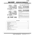
Reassembling the playback, recording and eraser heads (See Fig.3)
1. Reassemble the playback head from the front of the head mount to the position as shown in Fig.3. 2. Fix the reversing azimuth screw. 3. Set the spring a from behind the playback head. 4. Attach the flexible P.C.board to the chassis base as shown in Fig.3. 5. The recording and eraser heads should also be reassembled similarly according to Steps 1~4 above.
CN301 Head amplifier & mechanism control P.C. board Flywheel R
Fig.2
(Mechanism A side)
Playback head
Reversing azimuth screw Head mount Flexible P.C.board CN302
Spring "a"
FPC holder
Head amplifier & mechanism control
Fig.3
P.C. board (Mechanism B side)
1-26
|
|
|
> |
|