|
|
|
Who's Online
There currently are 5963 guests online. |
|
Categories
|
|
Information
|
|
Featured Product
|
|
|
 |
|
|
There are currently no product reviews.
 ;
This is a high quality manual with clear schematic and components layout diagrams ; with service procedure included.
 ;
This service manual for the Kenwood KT-990D was reproduced really well ,is very legible and manual is complete.Combined with the low price paid,in the future,I will be checking Owner-Manuals.com any time I need a manual.
;
When I purchased this manual I had my doubts regarding the quality as the price was so reasonable as compared to other outlets.
The manual itself is of high standard the print is very clear as are the diagrams. Obviously with the diagrams one has to zoom in otherwise it is to small to be able to read.
Overall I am very pleased with the company who delivered as they said and with the manual they supplied.
I occasionally require a manual and now having registered with this company I shall order from them in the future.
;
I was at first dubious about payiong for downloaded manuals but having done so, I was extremely impressed with quality of the two manual I ordered, well worth the small price I paid.
I would highly recommend these to my friends.
;
reasonable price for the schematic - the service is perfect, all as expected and pointed by instructions - good scan of the original plans - thank you!
MX-K5 Removing the heat sink & amp. board (See Fig.14 and 15)
Prior to performing the following procedure, remove the metal cover and the CD changer unit. 1. Remove the four screws I attaching the heat sink cover on the back of the body. Remove the heat sink cover. 2. Remove the four screws J attaching the heat sink & amp.board to the rear panel on the back of the body.
I
Heat sink cover
I
3. Remove the two screws K attaching the speaker terminal to the rear panel on the back of the body. 4. Disconnect the card wire from connector ACW1 & the harness from connector ACW2 on the amp. board. (See Fig.11) 5. After moving the heat sink upward, remove the claws. Then pull out the heat sink & amp.board inward.
Rear panel
Fig.14
Tuner terminal
J L
Removing the tuner board (See Fig.15 and 16)
Prior to performing the following procedure, remove the metal cover and CD changer unit. 1. Disconnect the card wire from connector CON01 on the tuner board. 2. Remove the two screws L attaching the tuner board.
Speaker terminal Heat sink
K J
Removing the rear cover
(See Fig.17)
Fig.15
Prior to performing the following procedure, remove the metal cover, CD changer unit, heat sink & amp.board and tuner pack.
Main board
1. Remove the four screws M attaching the rear panel. 2. Remove the screw M' attaching the voltage selector. (Only US/ UT/ UW)
CON01
Rear panel
M
Tuner board
Fig.16
M
M
Fig.17 1-9
 $4.99 MX-K5 JVC
Circuit Diagrams Set of circuit diagrams. The diagrams will be provided as PDF file. The file will be delivered after…  $4.99 MXK5 JVC
Owner's Manual Complete owner's manual in digital format. The manual will be available for download as PDF file aft… 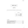 $4.99 MX-K5 JVC
Parts Catalog Parts Catalog only. It's available in PDF format. Useful, if Your equipment is broken and You need t…
|
|
|
> |
|