|
|
|
Who's Online
There currently are 5829 guests online. |
|
Categories
|
|
Information
|
|
Featured Product
|
|
|
 |
|
|
There are currently no product reviews.
 ;
Very good expirience with owner-manuals.com.
5 Stars; In future if necessary, i´ll download manuals on this site.
;
Hi - happy with what I received but not quite what I wanted - my fault I assumed that service manual would also include operational instructions which is what I needed - all I needed to know was how to turn the radio - thanks
;
this Manual very important when i buy this Manual i already fix the trouble of my Camera..... thanks keep up the good work.!
 ;
This service manual helped me to repair my PIONEER. Iam very satisfied, that I found it here.
Even the price of manual was not so high that person would not be able to spend a few money.
But that is very worth spent money. Thanks
;
Excellent quality service manual. Quick processing, fair prices. Love to do business again. Thank you!!!
MX-KA3
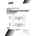
Removing the cassette deck heads (See Fig. 19 and 27)
Prior to performing the following procedures, remove the top cover and both sides board. Also remove the CD changer unit. Also remove the front panel assembly. 1. Remove six screws Z that retain the cassette deck mechanism. (Fig.19) 2. Remove the cassette deck mechanism and place it so that the front side faces up. 3. Remove the solder from the bottom side of the head terminal and disconnect the wire. 4. Remove screw U that retains the head. 5. Remove screw V that retains the head. 6. Hold the head and slide it in the direction of the arrow to remove it.
Cassette deck mechanism (Front side)
PB Head
V
U
V
U
REC/PB Head
Fig.27
Removing the 3-pin regulator and bridge diode (See Q904, Q907, D901, D914 and Fig.28)
Prior to performing the following procedures, remove the top cover and both sides board. 1. Remove two screws A that connect the heat sink. 2. Remove two screws W that connect the heat sink. 3. Remove the solder fixing the the 3-pin terminal regulator Q904, Q907. 4. Remove the solder fixing the 4-pin bridge diode (D901, D914).
W
A
Fig.28
1-16
|
|
|
> |
|