|
|
|
Who's Online
There currently are 5753 guests online. |
|
Categories
|
|
Information
|
|
Featured Product
|
|
|
 |
|
|
There are currently no product reviews.
 ;
Item as described, very well detailed manual with complete schematics. I've received the download information shortly after payment, very good support.
 ;
Really good and well scanned. File is complete the full service manual for 5$
;
Good product and very helpfull to repair. Many thanks.
;
Very good product. Best service manual. Many thanks
;
I am only search for 5 Minute, by it in 5 Minutes to and get ist in few ours! Best i found in the Internet and my Amplifer is repaired as well! Thank you
MX-KA6
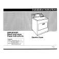
Removing the power amp and supply PCB and the power trans PCB (See Fig. 2, 29 to 31)
Prior to performing the following procedures, remove the top cover and CD changer unit. 1. Remove four screws B from the rear panel. (Fig.3) 2. Pull the heat sink cover outward. 3. Remove four screws AA from the rear panel between the heat sink holder. 4. Remove two screws X that retain the speaker terminals and AUX terminal. 5. Remove screws YY that retains the rear panel, and then remove the rear panel. 6. Disconnect the parallel wires from the connectors FW951 on the power trans PCB. 7. Remove the clamp of AC power cord from the chassis. 8. Remove four screws AB that retain the power trans PCB and then remove the assembly.
Fuse (F952) T3.15A 250V Fuse (F951) T1.6A 250V
AA
X
Fuse (F953) T1.25A 250V
Fig.29
Clamp
YY
Fig.30
Rear panel
AB Power amp and supply PCB
Chassis
Fig.31
1-17
 $4.99 MX-KA6 JVC
Circuit Diagrams Set of circuit diagrams. The diagrams will be provided as PDF file. The file will be delivered after…  $4.99 MX-KA6 JVC
Owner's Manual Complete owner's manual in digital format. The manual will be available for download as PDF file aft…  $4.99 MX-KA6 JVC
Parts Catalog Parts Catalog only. It's available in PDF format. Useful, if Your equipment is broken and You need t…
|
|
|
> |
|