|
|
|
Who's Online
There currently are 5891 guests online. |
|
Categories
|
|
Information
|
|
Featured Product
|
|
|
 |
|
|
There are currently no product reviews.
 ;
perfect copy, im very satisfied, i was need the diagram over the powersupply and
the copy was very sharp
;
This is exactly the service manual I needed.
Complete with all schematics, partslists, PCB layouts and alignment instructions.
This manual covers both the T-4970 en T-488F Onkyo tuner.
 ;
IF PRINTED CIRQUIT BOARD WIRING VIEW WAS ONE TONE LIGHTER, THEN 5 STAR RANK HAS TO BE MY CHOISE.
;
Very usefull, good quality drawings !
Muito útil encontrei todas as informações necessárias.
;
Wanting to repair a neighbours tape recorder I needed the necessary information, it makes it easier. Although the service manual is described as "Language : English" To my dismay I found that it is entirely written in German, a language I do not understand. At least I now have the schematics which will help of sorts. I may not use this service again due to the laguage difficulty after all when it states English you do not expect it to be entirely in another language.
PD-42DXT
DISPLAY INTERFACE PWB H
(x4)
E
(x6)
FILTER SHIELD
2.4.9 REMOVING THE PDP UNIT (Fig.5) � Remove the REAR COVER. � Remove the TERMINAL COVER. � Remove the CHASSIS BASE (with each PWB affixed on the CHASSIS BASE). (1) Remove the 4 screws [M], and remove the terminal bracket. (2) Disconnect the connectors of the following PWB. NOTE: � Disconnect the connector [CN0PW] from the LINE FILTER PWB. � Disconnect the connectors [CN0AU] and [CN0AT] from the PDP POWER PWB. � Disconnect the connector [CN0AH] and earth wire from the DISPLAY INTERFACE PWB. � It is advisable to take note of the connecting location (connector number) of the removed connectors. Remove the 4 screws [N] and 5 screws [O], and remove the 2 pieces of SUPPORT BRACKET (BOTTOM). Remove the 4 screws [P] and remove the 2 pieces of BACK FRAME (BOTTOM). Remove the 4 screws [Q] and 1 screw [R], and remove the 2 pieces of SUPPORT BRACKET (UPPER). Remove the 2 screws [S] and 1 screw [T], and remove the
PDP POWER PWB I
(x6)
F
(x4)
AUDIO PWB LINE FILTER PWB SYSTEM POWER PWB G
(x4)
(3) (4) (5)
INSULATOR SHEET
(6) Fig.3
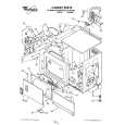
2.4.8 REMOVING THE CHASSIS BASE (Fig.4) � Remove the REAR COVER. � � � � � � Remove the TERMINAL COVER. Remove the FILTER SHIELD and LINE FILTER PWB. Remove the AUDIO PWB. Remove the SYSTEM POWER PWB. Remove the DISPLAY INTERFACE PWB. Remove the PDP POWER PWB. (1) Remove the 2 screws [J] and 1 screw [K]. (2) Lift upwards and withdraw the AC inlet in a front direction. (3) Remove the 4 screws [L], and remove the CHASSIS BASE.
panel shield. (7) Remove the 4 screws [U]. (8) Life the PDP upright and remove it with enough care not to impose shock to the PDP. Caution: � Two or more people are required to remove the PDP unit � The gas pouring port is covered with the protection material.In operation, be careful not to damage the gas pouring port. � Do not touch the front side (glass) of the PDP with your fingers.
CHASSIS BASE
L
(x4)
K
J
(x2)
AC INLET COVER
Fig.4
(No.52108)1-11
 $4.99 PD-42DXT JVC
Parts Catalog Parts Catalog only. It's available in PDF format. Useful, if Your equipment is broken and You need t…
|
|
|
> |
|